HP MicroServer Gen8: two PCIe, too furious

The HP ProLiant MicroServer Gen8 was quite the impressive budget server when it was released in 2013.
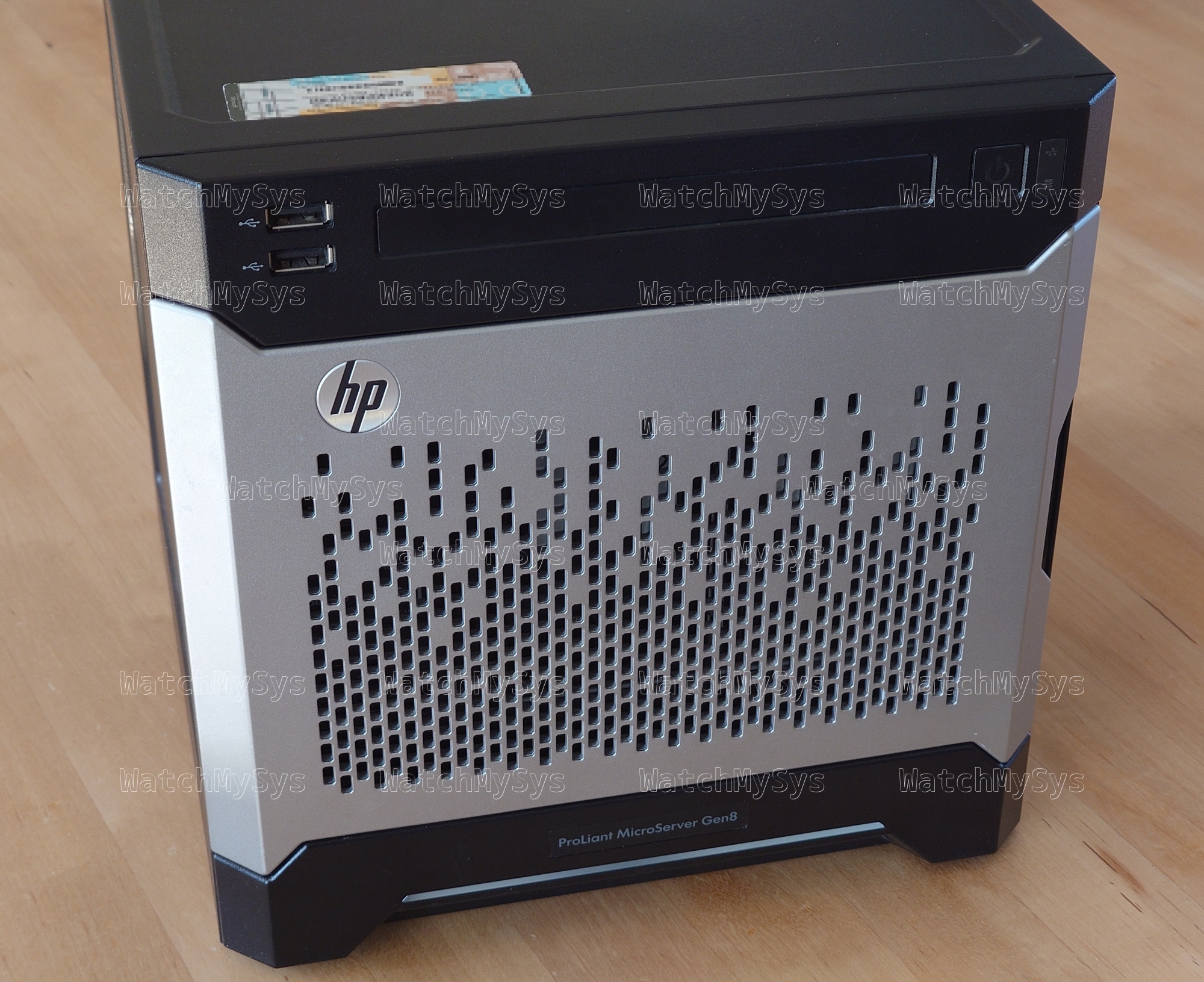
Behold the power of some CPU cores, a maximum of 16GB of DDR3 RAM, and 4 to ?? disks

Intel was dominating desktop CPUs, and a typical desktop or workstation motherboard of this era had a single PCIe 3.0 x16 slot, and then several PCIe 2.0 slots (e.g. x4 and x1). The MicroServer Gen8, due to its small size (slightly larger than ITX), was limited to only one PCIe 2.0 x16 slot. You also did not have the option to bifurcate the PCIe x16 slot, as is common in recent years.

At least, that is what everyone thought. This adventure started when I found a very interesting blog post about bifurcating the PCIe x16 slot on Intel socket 1155:

As mentioned above, I want to set 16=8+4+4, so the values of CFG[5] and CFG[6] should be both 0. So we can ground CFG[5] and CFG[6] by connecting N35M35 and L37M37. (VSS is GND, and VCC is PWR)

This information is from the Desktop 3rd Generation Intel® Core™ Processor Family, Desktop Intel® Pentium® Processor Family, and Desktop Intel® Celeron® Processor Family datasheet:
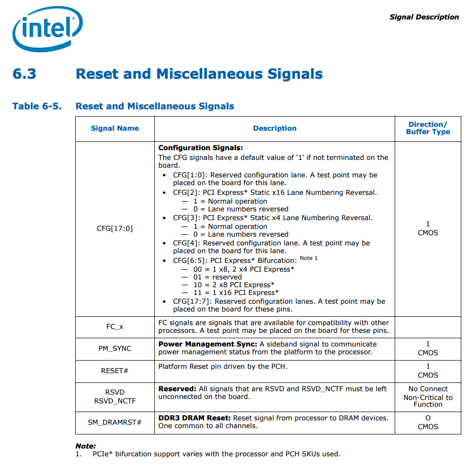
Desktop 3rd Generation Intel® Core™ Processor Family, Desktop Intel® Pentium® Processor Family, and Desktop Intel® Celeron® Processor Family

The author found that by physically bridging the pads corresponding to CFG[5] and CFG[6] they could force the PCIe x16 slot to bifurcate into x8x4x4. Since there is no official support for PCIe bifurcation on the Ivy Bridge generation, this was an interesting finding and one which I feel went largely unnoticed.

The author used silver paste, which is more permanent than what I wanted. I decided to go a more reversible route: using kapton tape and very thin strips of aluminum foil (precision cut with Fiskars scissors from a roll of baking foil).
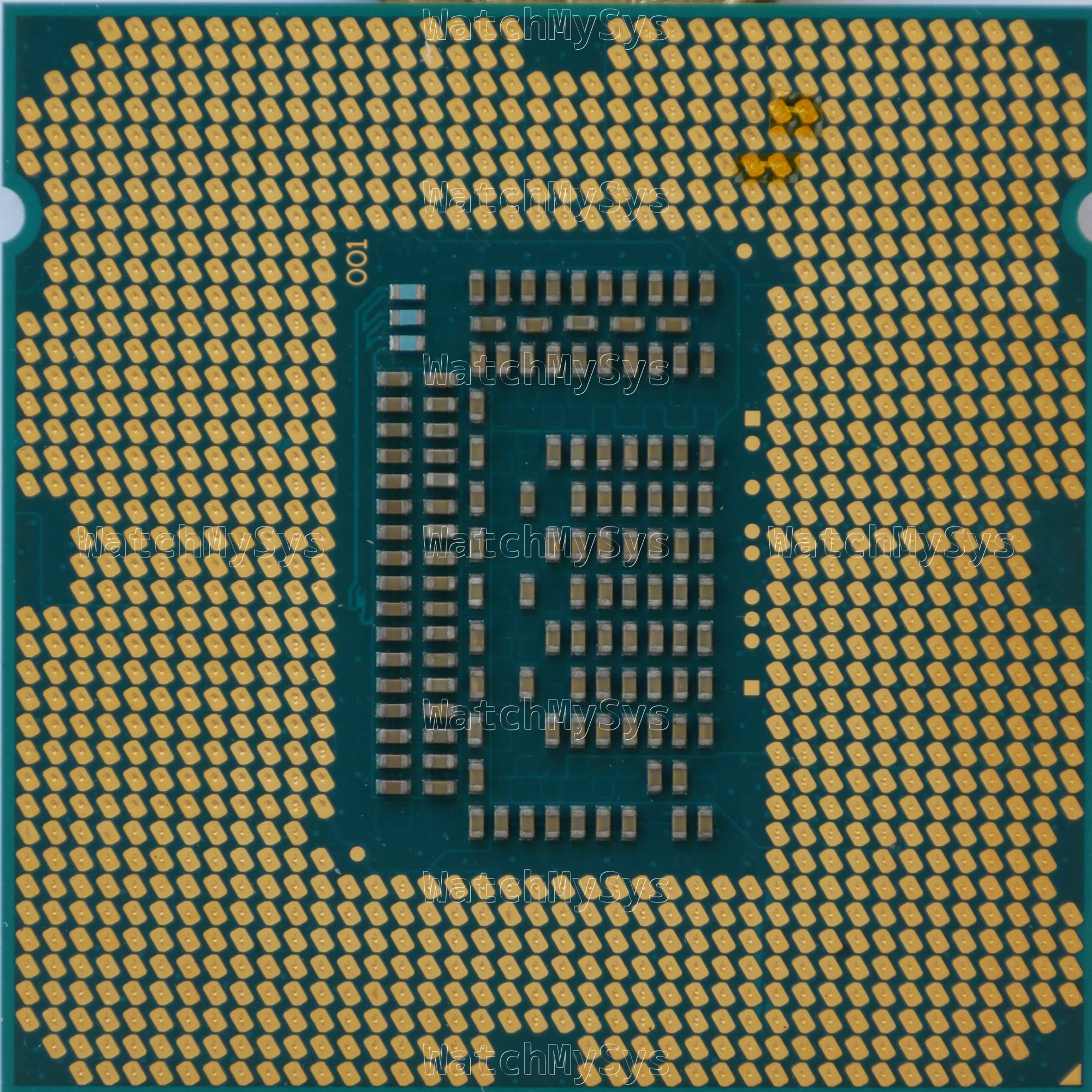
LGA1155 CPU modified for x8x4x4 bifurcation

It is important to note that by default CFG[5] and CFG[6] are pulled up to 1. Masking the pads with kapton tape is ineffective, they must be grounded to an adjacent GND pad.

WARNING: You can cause permanent damage to your CPU and motherboard by bridging incorrect pads. Always verify that the pads you have bridged are correct before installing the CPU into the socket.

So, I obtained HP MicroServer Gen8 and got to work testing this.
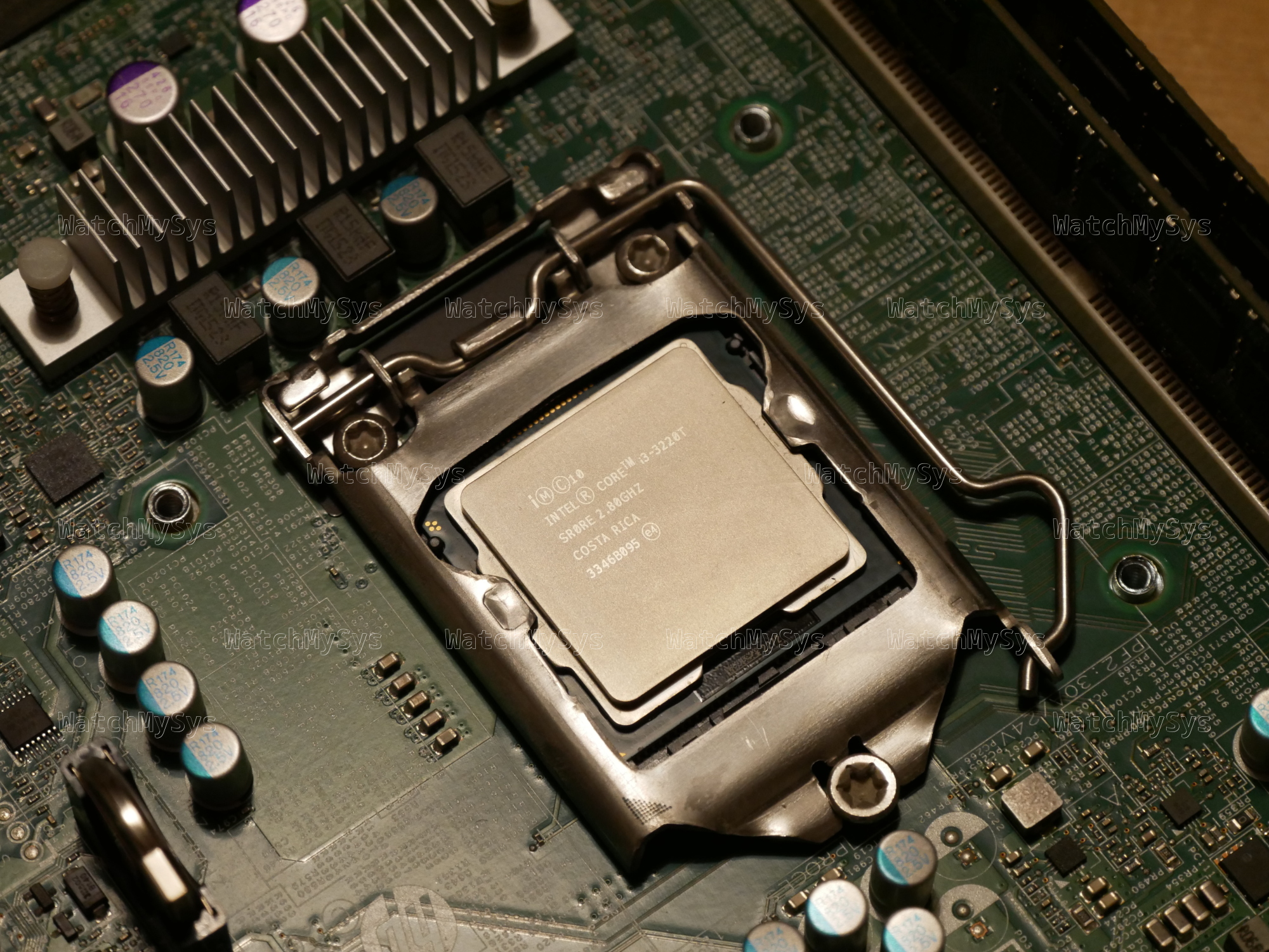
Bridging both CFG[5] and CFG[6] for x8x4x4 resulted in the system hanging indefinitely during the “Processor Initialization Complete” step in POST.
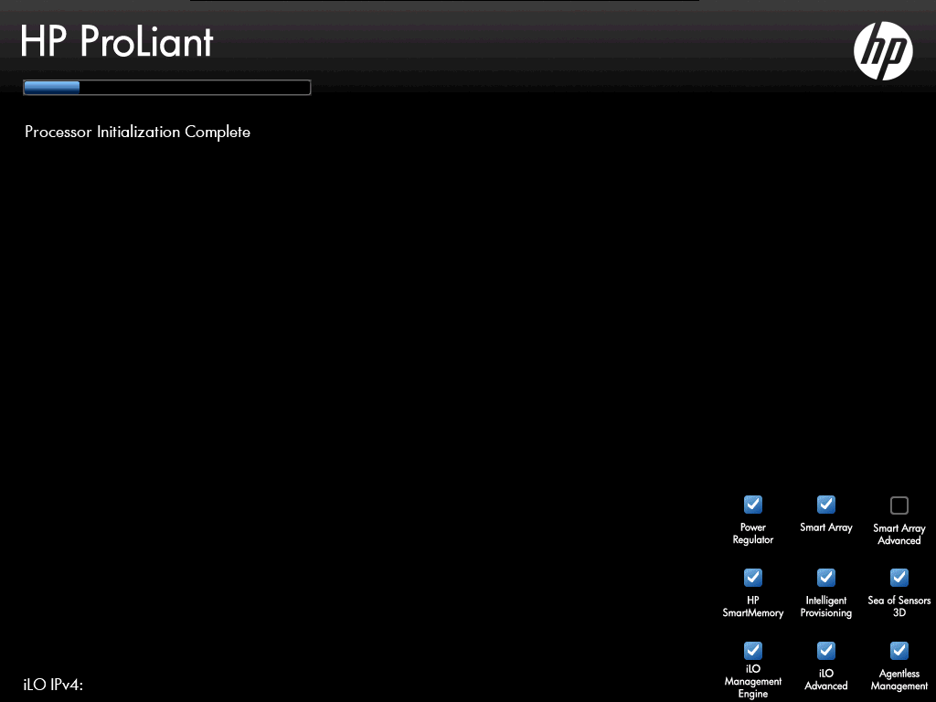
HP MicroServer Gen8 BIOS POST screen

Boot stuck at “Processor Initialization Complete”

Bridging only CFG[5] to set bifurcation to x8x8 did work, and the system passed POST.
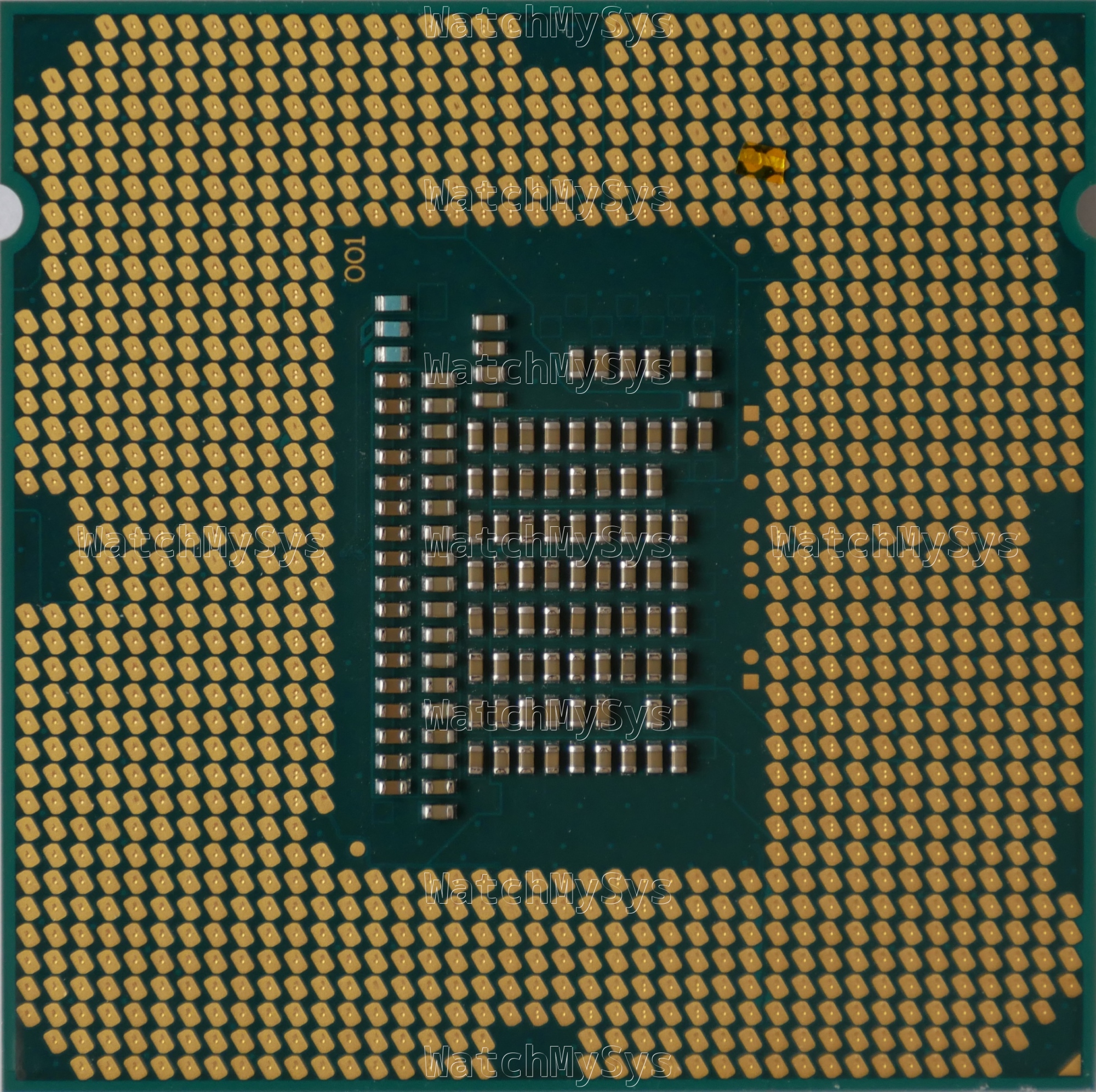
LGA1155 CPU modified for x8x8 bifurcation

With this modification, you can install two PCIe devices in the PCIe x16 slot of the MicroServer Gen8. Unfortunately due to physical constraints in the chassis, it is not possible to install a half height card on top of a half height riser (e.g. x8 and dual NVMe) but you can install a dual or quad NVMe adapter and use two PCIe x4 lanes (e.g. for an M.2 SATA controller and an M.2 2.5/5G NIC). If you do not mind PCIe cards hanging out the side, you can use a dual x8 riser like the one pictured below.
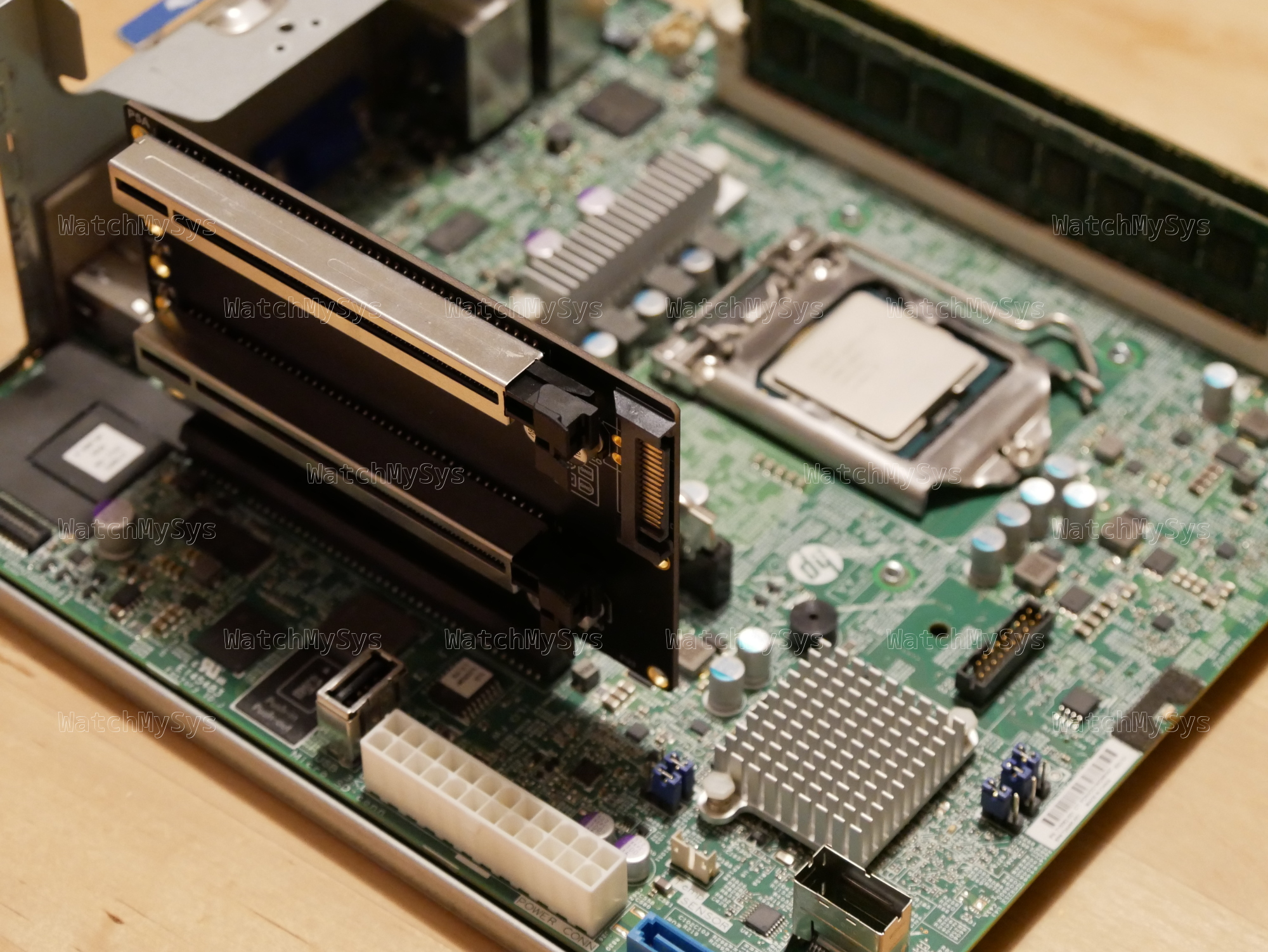
HP MicroServer Gen8 with x8x8 riser installed

Here is the lspci output of two ConnectX-3 Pro 40G network cards installed in a MicroServer Gen8:

# lspci
00:00.0 Host bridge: Intel Corporation Xeon E3-1200 v2/3rd Gen Core processor DRAM Controller (rev 09)
00:01.0 PCI bridge: Intel Corporation Xeon E3-1200 v2/3rd Gen Core processor PCI Express Root Port (rev 09)
00:01.1 PCI bridge: Intel Corporation Xeon E3-1200 v2/3rd Gen Core processor PCI Express Root Port (rev 09)
00:06.0 PCI bridge: Intel Corporation Xeon E3-1200 v2/3rd Gen Core processor PCI Express Root Port (rev 09)
00:1a.0 USB controller: Intel Corporation 6 Series/C200 Series Chipset Family USB Enhanced Host Controller #2 (rev 05)
00:1c.0 PCI bridge: Intel Corporation 6 Series/C200 Series Chipset Family PCI Express Root Port 1 (rev b5)
00:1c.4 PCI bridge: Intel Corporation 6 Series/C200 Series Chipset Family PCI Express Root Port 5 (rev b5)
00:1c.6 PCI bridge: Intel Corporation 6 Series/C200 Series Chipset Family PCI Express Root Port 7 (rev b5)
00:1c.7 PCI bridge: Intel Corporation 6 Series/C200 Series Chipset Family PCI Express Root Port 8 (rev b5)
00:1d.0 USB controller: Intel Corporation 6 Series/C200 Series Chipset Family USB Enhanced Host Controller #1 (rev 05)
00:1e.0 PCI bridge: Intel Corporation 82801 PCI Bridge (rev a5)
00:1f.0 ISA bridge: Intel Corporation C204 Chipset LPC Controller (rev 05)
00:1f.2 SATA controller: Intel Corporation 6 Series/C200 Series Chipset Family 6 port Desktop SATA AHCI Controller (rev 05)
01:00.0 System peripheral: Hewlett-Packard Company Integrated Lights-Out Standard Slave Instrumentation & System Support (rev 05)
01:00.1 VGA compatible controller: Matrox Electronics Systems Ltd. MGA G200EH
01:00.2 System peripheral: Hewlett-Packard Company Integrated Lights-Out Standard Management Processor Support and Messaging (rev 05)
01:00.4 USB controller: Hewlett-Packard Company Integrated Lights-Out Standard Virtual USB Controller (rev 02)
03:00.0 Ethernet controller: Broadcom Inc. and subsidiaries NetXtreme BCM5720 Gigabit Ethernet PCIe
03:00.1 Ethernet controller: Broadcom Inc. and subsidiaries NetXtreme BCM5720 Gigabit Ethernet PCIe
04:00.0 USB controller: Renesas Technology Corp. uPD720201 USB 3.0 Host Controller (rev 03)
07:00.0 Ethernet controller: Mellanox Technologies MT27520 Family [ConnectX-3 Pro]
0a:00.0 Ethernet controller: Mellanox Technologies MT27520 Family [ConnectX-3 Pro]

Of course the MicroServer Gen8 is very under powered and can only dream of saturating even a single 40G link.

# lspci -s 07:00.0 -vvv
07:00.0 Ethernet controller: Mellanox Technologies MT27520 Family [ConnectX-3 Pro]
        Subsystem: Hewlett-Packard Company InfiniBand FDR/Ethernet 10Gb/40Gb 2-port 544+FLR-QSFP Adapter
        Physical Slot: 1
        Control: I/O- Mem+ BusMaster+ SpecCycle- MemWINV- VGASnoop- ParErr+ Stepping- SERR- FastB2B- DisINTx+
        Status: Cap+ 66MHz- UDF- FastB2B- ParErr- DEVSEL=fast >TAbort- <TAbort- SERR- <PERR- INTx-
        Latency: 0, Cache Line Size: 64 bytes
        Interrupt: pin A routed to IRQ 16
        Region 0: Memory at fbe00000 (64-bit, non-prefetchable) [size=1M]
        Region 2: Memory at f6000000 (64-bit, prefetchable) [size=32M]
        (...)
        Capabilities: [60] Express (v2) Endpoint, IntMsgNum 0
                DevCap: MaxPayload 512 bytes, PhantFunc 0, Latency L0s <64ns, L1 unlimited
                        ExtTag- AttnBtn- AttnInd- PwrInd- RBE+ FLReset+ SlotPowerLimit 116W TEE-IO-
                DevCtl: CorrErr- NonFatalErr+ FatalErr+ UnsupReq-
                        RlxdOrd- ExtTag- PhantFunc- AuxPwr- NoSnoop- FLReset-
                        MaxPayload 256 bytes, MaxReadReq 4096 bytes
                DevSta: CorrErr+ NonFatalErr- FatalErr- UnsupReq+ AuxPwr- TransPend-
                LnkCap: Port #8, Speed 8GT/s, Width x8, ASPM L0s, Exit Latency L0s unlimited
                        ClockPM- Surprise- LLActRep- BwNot- ASPMOptComp+
                LnkCtl: ASPM Disabled; RCB 64 bytes, LnkDisable- CommClk+
                        ExtSynch- ClockPM- AutWidDis- BWInt- AutBWInt-
                LnkSta: Speed 5GT/s (downgraded), Width x8
                        TrErr- Train- SlotClk+ DLActive- BWMgmt- ABWMgmt-
                DevCap2: Completion Timeout: Range ABCD, TimeoutDis+ NROPrPrP- LTR-
                         10BitTagComp- 10BitTagReq- OBFF Not Supported, ExtFmt- EETLPPrefix-
                         EmergencyPowerReduction Not Supported, EmergencyPowerReductionInit-
                         FRS- TPHComp- ExtTPHComp-
                         AtomicOpsCap: 32bit- 64bit- 128bitCAS-
                DevCtl2: Completion Timeout: 50us to 50ms, TimeoutDis-
                         AtomicOpsCtl: ReqEn-
                         IDOReq- IDOCompl- LTR- EmergencyPowerReductionReq-
                         10BitTagReq- OBFF Disabled, EETLPPrefixBlk-
                LnkCap2: Supported Link Speeds: 2.5-8GT/s, Crosslink- Retimer- 2Retimers- DRS-
                LnkCtl2: Target Link Speed: 8GT/s, EnterCompliance- SpeedDis-
                         Transmit Margin: Normal Operating Range, EnterModifiedCompliance- ComplianceSOS-
                         Compliance Preset/De-emphasis: -6dB de-emphasis, 0dB preshoot
                LnkSta2: Current De-emphasis Level: -6dB, EqualizationComplete- EqualizationPhase1-
                         EqualizationPhase2- EqualizationPhase3- LinkEqualizationRequest-
                         Retimer- 2Retimers- CrosslinkRes: unsupported
        (...)
        Kernel driver in use: mlx4_core
        Kernel modules: mlx4_core
# lspci -s 0a:00.0 -vvv
0a:00.0 Ethernet controller: Mellanox Technologies MT27520 Family [ConnectX-3 Pro]
        Subsystem: Hewlett-Packard Company InfiniBand FDR/Ethernet 10Gb/40Gb 2-port 544+FLR-QSFP Adapter
        Control: I/O- Mem+ BusMaster+ SpecCycle- MemWINV- VGASnoop- ParErr+ Stepping- SERR- FastB2B- DisINTx+
        Status: Cap+ 66MHz- UDF- FastB2B- ParErr- DEVSEL=fast >TAbort- <TAbort- SERR- <PERR- INTx-
        Latency: 0, Cache Line Size: 64 bytes
        Interrupt: pin A routed to IRQ 16
        Region 0: Memory at fbf00000 (64-bit, non-prefetchable) [size=1M]
        Region 2: Memory at f8000000 (64-bit, prefetchable) [size=32M]
        (...)
        Capabilities: [60] Express (v2) Endpoint, IntMsgNum 0
                DevCap: MaxPayload 512 bytes, PhantFunc 0, Latency L0s <64ns, L1 unlimited
                        ExtTag- AttnBtn- AttnInd- PwrInd- RBE+ FLReset+ SlotPowerLimit 116W TEE-IO-
                DevCtl: CorrErr- NonFatalErr+ FatalErr+ UnsupReq-
                        RlxdOrd- ExtTag- PhantFunc- AuxPwr- NoSnoop- FLReset-
                        MaxPayload 128 bytes, MaxReadReq 4096 bytes
                DevSta: CorrErr- NonFatalErr- FatalErr- UnsupReq- AuxPwr- TransPend-
                LnkCap: Port #8, Speed 8GT/s, Width x8, ASPM L0s, Exit Latency L0s unlimited
                        ClockPM- Surprise- LLActRep- BwNot- ASPMOptComp+
                LnkCtl: ASPM Disabled; RCB 64 bytes, LnkDisable- CommClk+
                        ExtSynch- ClockPM- AutWidDis- BWInt- AutBWInt-
                LnkSta: Speed 5GT/s (downgraded), Width x8
                        TrErr- Train- SlotClk+ DLActive- BWMgmt- ABWMgmt-
                DevCap2: Completion Timeout: Range ABCD, TimeoutDis+ NROPrPrP- LTR-
                         10BitTagComp- 10BitTagReq- OBFF Not Supported, ExtFmt- EETLPPrefix-
                         EmergencyPowerReduction Not Supported, EmergencyPowerReductionInit-
                         FRS- TPHComp- ExtTPHComp-
                         AtomicOpsCap: 32bit- 64bit- 128bitCAS-
                DevCtl2: Completion Timeout: 50us to 50ms, TimeoutDis-
                         AtomicOpsCtl: ReqEn-
                         IDOReq- IDOCompl- LTR- EmergencyPowerReductionReq-
                         10BitTagReq- OBFF Disabled, EETLPPrefixBlk-
                LnkCap2: Supported Link Speeds: 2.5-8GT/s, Crosslink- Retimer- 2Retimers- DRS-
                LnkCtl2: Target Link Speed: 8GT/s, EnterCompliance- SpeedDis-
                         Transmit Margin: Normal Operating Range, EnterModifiedCompliance- ComplianceSOS-
                         Compliance Preset/De-emphasis: -6dB de-emphasis, 0dB preshoot
                LnkSta2: Current De-emphasis Level: -6dB, EqualizationComplete- EqualizationPhase1-
                         EqualizationPhase2- EqualizationPhase3- LinkEqualizationRequest-
                         Retimer- 2Retimers- CrosslinkRes: unsupported
        (...)
        Kernel driver in use: mlx4_core
        Kernel modules: mlx4_core

To anyone still running a MicroServer Gen8 and would like more expansion, I hope you find this information useful.
Meraki MX75 hardware overview

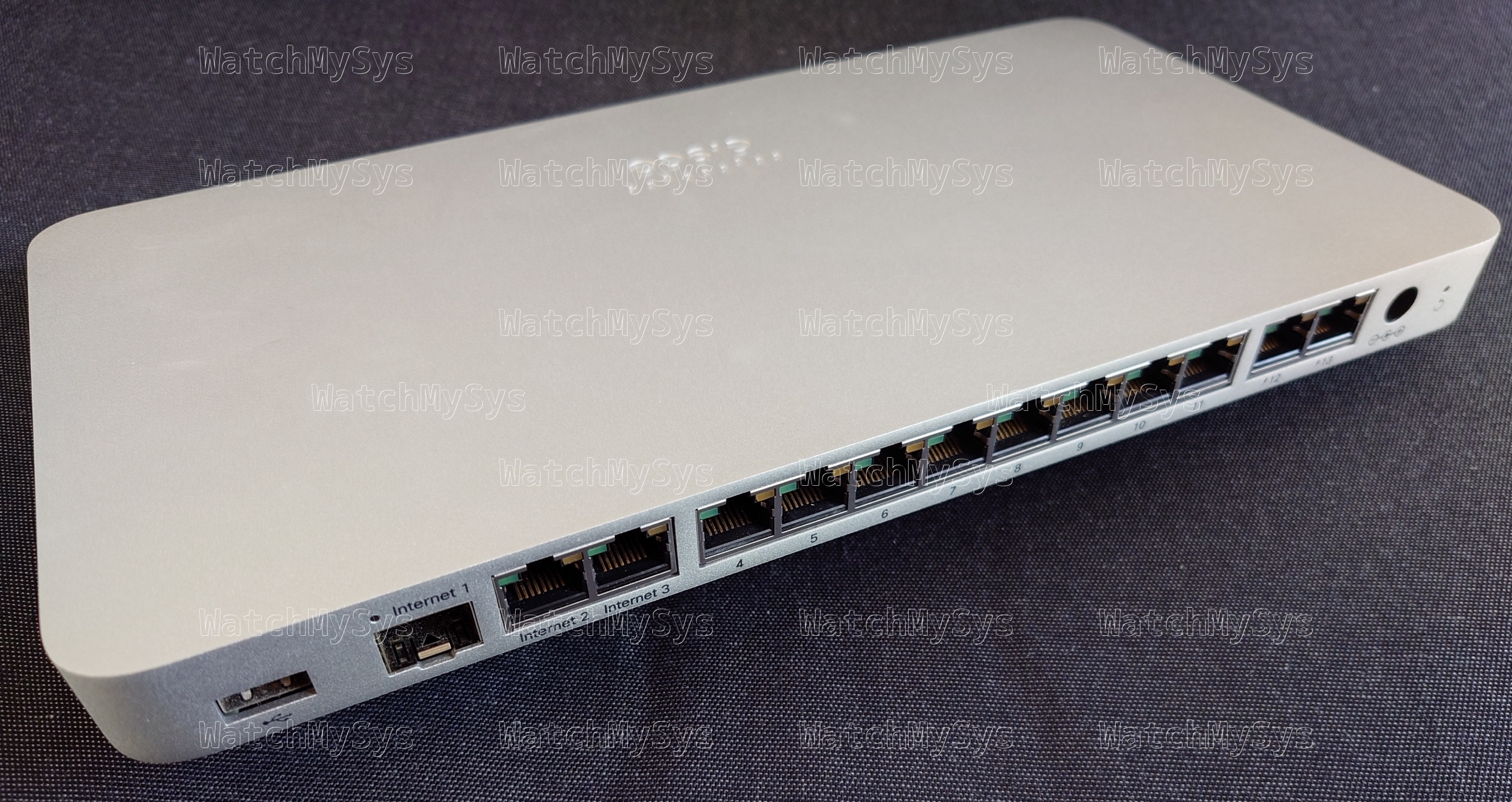
The Meraki MX75 SD-WAN appliance (codename “Barley Wine”) offers 3 WAN uplink ports (1 SFP, 2 Gigabit Ethernet), 10 LAN ports (8 Gigabit Ethernet, 2 PoE), and a USB 3.0 port for external cellular modems¹.

Meraki MX75 SD-WAN appliance

Here is a summary of the MX75 specs:

  • NXP LayerScape LS1046A (ARM A72, 4 cores @ 1.8GHz)
  • 4GB DDR4 RAM (Micron MT40A512M16LY-075:E running at 2100MT/s, 4 chips, soldered)
  • 16GB of EMMC flash (SanDisk SDINBDA6-16G)
  • Winbond W25Q64JVSIQ, MXIC MX25U6472F
  • Aikido/Cisco TAM hardware root-of-trust (Microchip SmartFusion2 M2S010)
  • Qualcomm QCA8337-AL3C 7-port Gigabit Ethernet Switch (x2, PDF datasheet)
  • Qualcomm QCA8334-AL3C 4-port Gigabit Ethernet Switch (PDF datasheet)
  • Microchip PD69104B1 PSE controller (PoE LAN ports)
  • Sunon EG60070S1-C200-S9A fan
  • UMEC 100W power supply (MA-PWR-100WAC)

Unlike the MX85, the MX75 has no dedicated management port.

The MX75 also does not support PoE output on any of the WAN ports; Meraki sales need some justification to upsell customers to an MX85! (Public service reminder that PoE injectors exist and are considerably less expensive than the cost difference from an MX75 to an MX85)


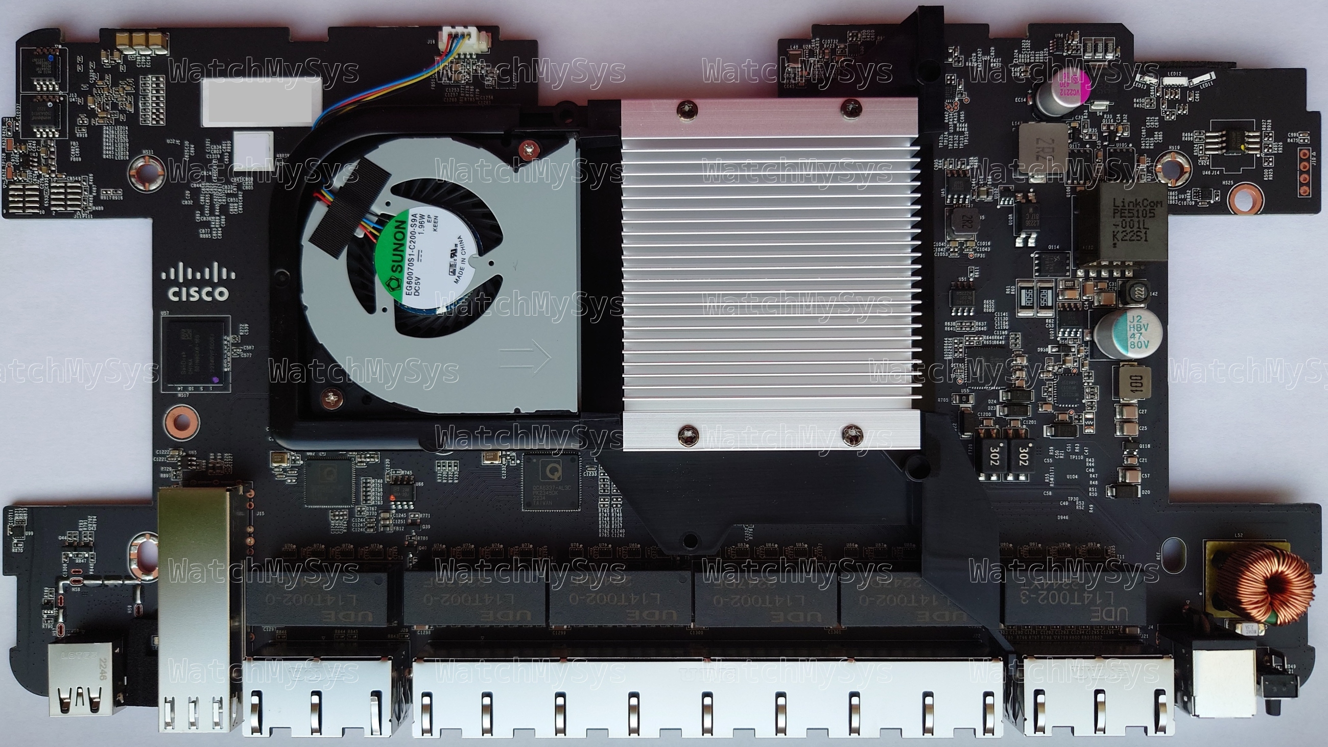
Meraki MX75 PCB

Meraki MX75 PCB

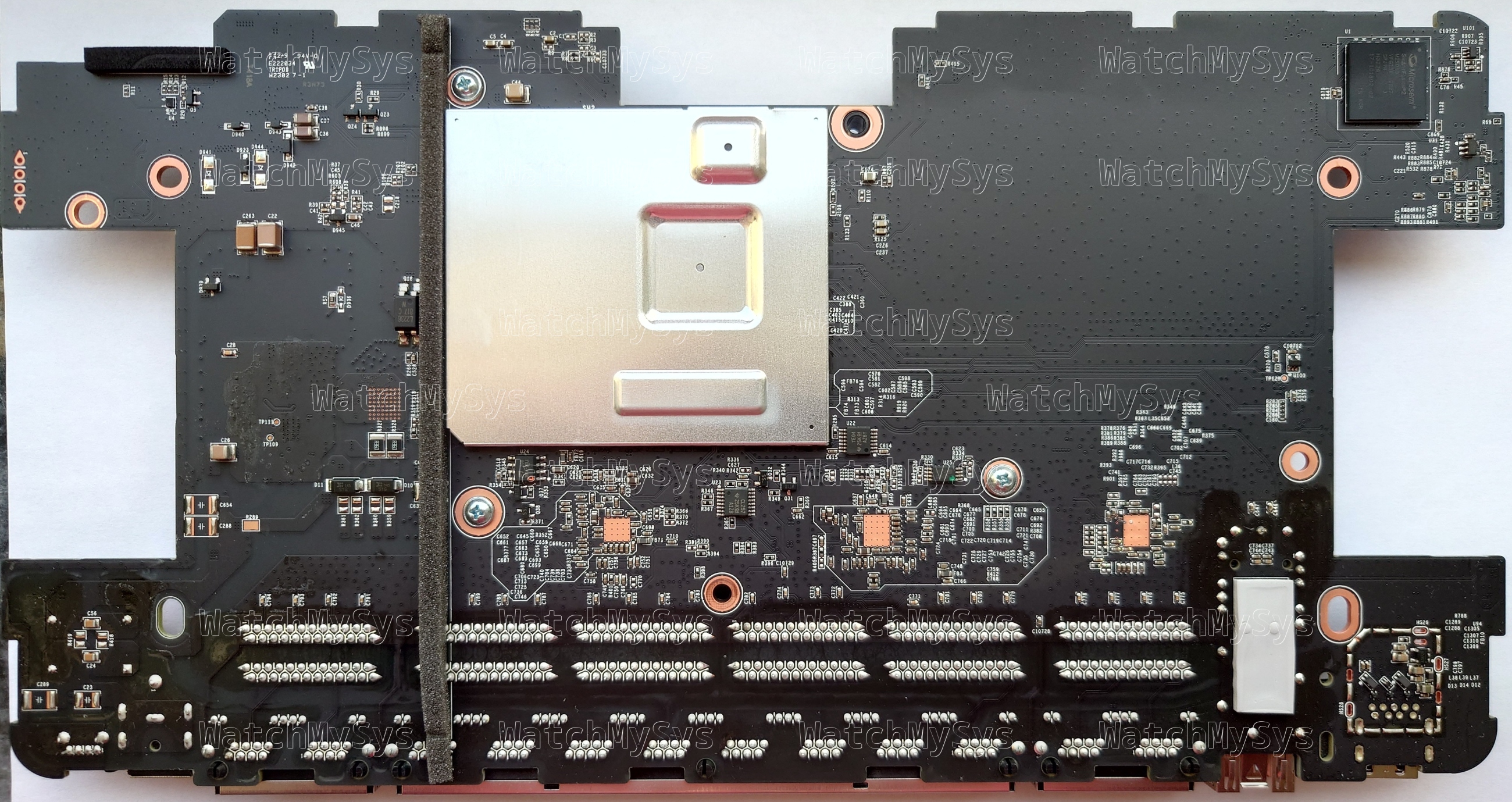
The MX75 uses the same LS1046A found in the passively cooled MX85, but has active cooling via a Sunon EG60070S1-C200-S9A fan. The thermal pad sales department definitely earned their quarterly bonus for this design win, because the MX75 has thermal pads above and below the metal EMI shield: 1.8mm (twice) for the memory and 1.2mm (twice) for the CPU. I offer this humble edit to the MX75 mounting instructions:

Please make sure there are no blockages or obstructions within one inch of the top of the chassis or within 0.5 inches of the sides so that nothing [except our overzealous use of thermal pads] interferes with cooling.


The UART header is J10 on the MX75 and follows the standard Meraki UART pinout (1: Vcc, 2: Tx, 3: Rx, 4: GND) at 3.3V and 115200 baud. Unlike the MX85 there are no resistors are missing, so just solder the 2.54mm header or use pogo pins.

MX75 PCB bottom

MX75 PCB bottom


The U-Boot release on the MX75 is 2018.09julia-spl-dandybar and, like all other recent Meraki products, it does not allow interrupting boot.

U-Boot SPL 2018.09julia-spl-dandybar (Mar 16 2021 - 00:27:48 +0000)
Initializing DDR....using SPD
Trying to boot from BOOTROM

U-Boot 2018.09julia-spl-dandybar (Mar 16 2021 - 00:27:48 +0000)

SoC:  LS1046AE Rev1.0 (0x87070010)
Clock Configuration:
       CPU0(A72):1800 MHz  CPU1(A72):1800 MHz  CPU2(A72):1800 MHz  
       CPU3(A72):1800 MHz  
       Bus:      700  MHz  DDR:      2100 MT/s  FMAN:     800  MHz
Reset Configuration Word (RCW):
       00000000: 0e150012 10000000 00000000 00000000
       00000010: 33330000 00b00012 40000000 c1000000
       00000020: 00000000 00000000 00000000 00018ffc
       00000030: 20004504 05003000 00000096 00000001
Model: LS1046A RDB Board
Board: LS1046ARDB, boot from Invalid setting of SW5
CPLD:  V0.0
PCBA:  V0.0
SERDES Reference Clocks:
SD1_CLK1 = 100.00MHZ, SD1_CLK2 = 100.00MHZ
I2C:   ready
DRAM:  Detected UDIMM Fixed DDR on board
3.9 GiB (DDR4, 64-bit, CL=15, ECC off)
SEC0: RNG instantiated
PPA Firmware: Version LSDK-18.09
GPIO:	initialized
setting up RGB LED controller lp5562....
LM96163:	initialized
Using SERDES1 Protocol: 13107 (0x3333)
Using SERDES2 Protocol: 0 (0x0)
SERDES2[PRTCL] = 0x0 is not valid
NAND:  0 MiB
MMC:   FSL_SDHC: 0
EEPROM: meraki_MX75 600-103010
In:    serial
Out:   serial
Err:   serial
Net:   Invalid SerDes protocol 0x3333 for LS1046ARDB
Fman1: Uploading microcode version 108.4.9
Could not get PHY for MDIO1: addr 1
Failed to connect
Could not get PHY for MDIO2: addr 3
Failed to connect
Could not get PHY for MDIO2: addr 5
Failed to connect
PCIe0: pcie@3400000 disabled
PCIe1: pcie@3500000 disabled
PCIe2: pcie@3600000 disabled
FM1@DTSEC3 [PRIME], FM1@DTSEC5, FM1@DTSEC6, FM1@DTSEC9, FM1@DTSEC10

As we can see from the above ECC off output, the MX75 is using non-ECC RAM. This is similar to the MX65 which also did not include ECC memory. To my knowledge, no Meraki ARM-based designs incorporate ECC memory.

The MX75 also contains the Cisco TAM, implemented using a SmartFusion2 M2S010. The TAM is used for secure boot.

----Security Versions----
SecureBoot:  R6.3.101-42a1499-20201106
SB Core:     F01257R21.039b56e6b2020-06-29
Microloader: MK0007R01.0105062020
SF: Detected SPI Generic with page size 256 Bytes, erase size 4 KiB, total 16 MiB

----SecureBoot Registers----
system_invalid:            0
boot_check_count_error:    0
boot_done:                 1
boot_ok:                   1
boot_check_count_golden:   0
boot_check_count_upgrade:  2
boot_status_golden:        0
boot_status_upgrade:       1
first_bootloader:          1

----Upgrade----
boot_error:                0
boot_check_count_error_vc: 0
boot_check_count_error:    0
boot_timeout_vc:           0
boot_timeout:              0
boot_cs_good:              1
boot_config_error:         0
boot_version_error:        0
boot_config_error_code:    0
boot_error_code:           0
boot_cs_good:              1
boot_version_error:        0
boot1_cs_key_type:         1
boot1_cs_return_code:      0
boot1_cs_key_index:        5
boot2_cs_return_code:      0
boot2_cs_key_index:        5
boot2_cs_key_type:         1

----Other Registers----
fpga_version:      0090

Reading whitelist from TAM
whitelist.bin: 744 bytes

Converting whitelist to signature fdt
BARLEY-WINE_LDWM-rel
wired-arm64-OD-SECP384R1_1-rel
wired-arm64-RT-SECP384R1_1-rel
wired-arm64-AP-SECP384R1_1-rel
wrote 558 bytes to 0000000082330000

Same story as the MX85, do not expect any OpenWrt support for this device.


Idle power consumption: ~15W

The MA-PWR-100WAC power supply (P/N: 640-76010) is manufactured by UMEC and outputs 54V @ 1.85A with a 6.5 x 3.0 mm center-positive barrel tip on a 175 cm long cable. It weighs 553g (without C13 cable) and has dimensions 170 x 70 x 40 mm.

The MA-PWR-100WAC power supply is physically larger and heavier than the MA-PWR-90WAC (427g, 153 x 65 x 36 mm) so it is more than an uprated version of the 90W power supply.


Model Codename Part number
MX75 Barley Wine 600-103010

There are references to an MX75W in the firmware, however it appears this model was never publicly released. Certainly it would require a different PCB, as there are no unpopulated components on the MX75 PCB for a wireless radio or antennas.

The MX75 unit weighs 840g.


¹: USB modems with MX/Z series devices running firmware MX 18 or newer will be limited to best effort support and will not be receiving any future firmware fixes or improvements. Meraki documentation

It would seem that Meraki prefers their customers purchase an MG41 or MG51 than plug in their own USB LTE modem. Better margins and less to support, win-win!


The GPL source code for the MX75 was requested from Meraki in September 2024. At the time of writing Meraki has not provided any of the requested source code.

Meraki MS425 hardware overview

The Meraki MS425 series switches (codename “Hungry Hungry Hippo”) offer 16 or 32 ports of 10Gbit SFP+ Ethernet, two 40Gbit QSFP+ stacking ports, and a Gigabit Ethernet management port.

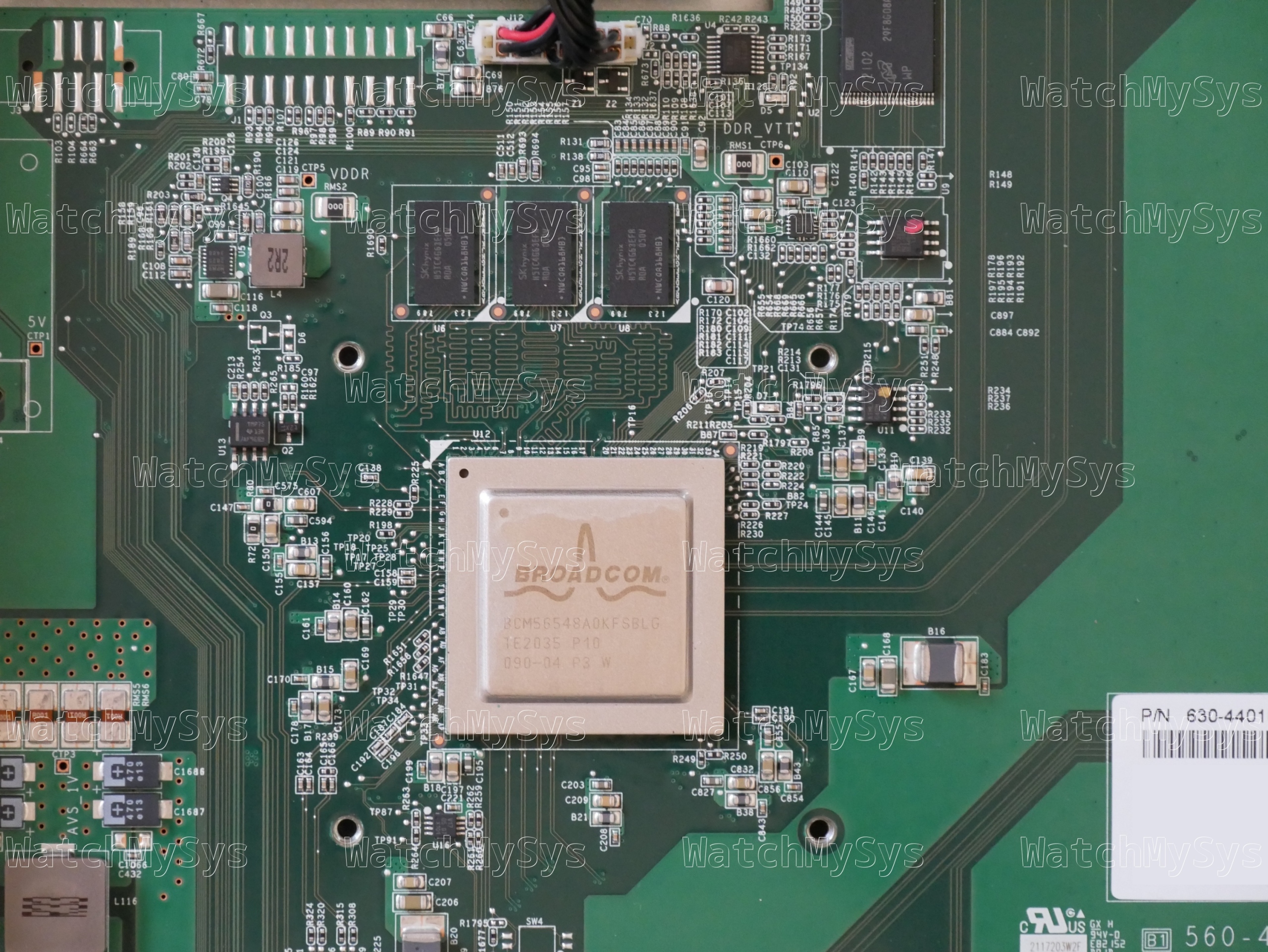
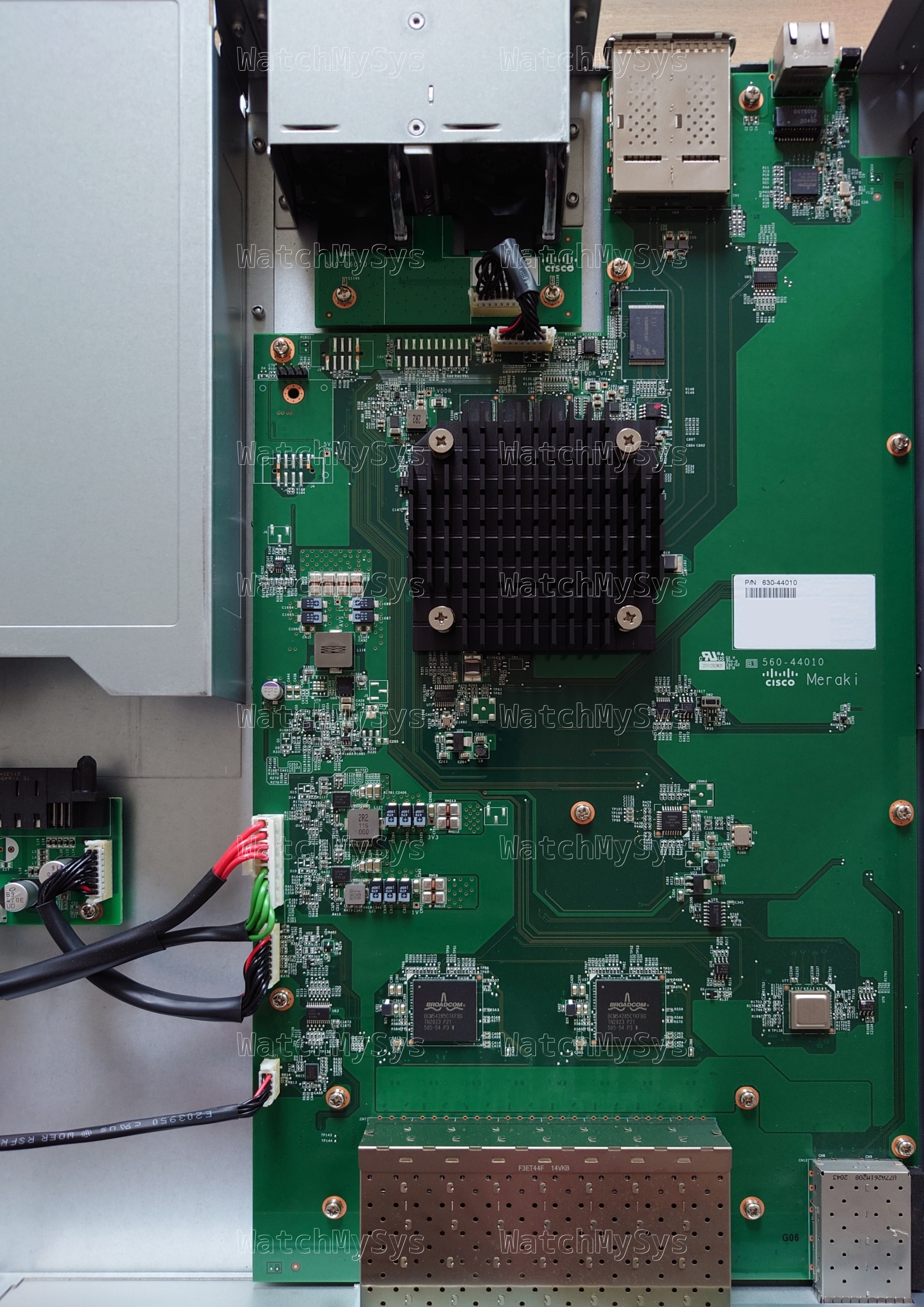
Meraki MS425-16 Switch with cover removed

Meraki MS425-16 internal view

The MS425 was discontinued in June 2024, and is too old to support secure boot.

Here is a quick summary of the MS425 specs:

  • Broadcom BCM56854 “Trident II” ASIC
  • Broadcom BCM5862x “StrataGX” management CPU
  • 16MB of SPI flash (MX25L12805D)
  • 2GB DDR3 RAM (soldered)
  • 1024MB NAND flash (Micron MT29F8G08ABACA; PDF datasheet)
  • MA-PWR-250WAC (identical to PWR-C2-250WAC)

The UART header in the MS425 is CONN7 (silk screen: UART Console) and follows the standard Meraki UART pinout (1: 3.3V Vcc, 2: Tx, 3: Rx, 4: GND) at 115200 baud.

The MS425-16 uses the same PCB as the MS425-32, but missing 16 SFP+ cages and two PHYs. This is the same technique Meraki used for the MS420-24 model.


The stock Meraki boot process uses u-boot on SPI to load a “bootkernel” (also from SPI), which then initializes NAND and using kexec boots the main firmware. The firmware layout follows the standard Meraki practice of having A/B firmware images: bootkernel1, bootkernel2, part.safe, part.old.

The firmware layout on SPI is:

0x000000-0x100000 : "uboot"
0x100000-0x800000 : "bootkernel1"
0x800000-0xf00000 : "bootkernel2"

Unlike the MS350, the management plane is not an x86 CPU, but a Broadcom “StrataGX” ARMv7. The MS425 runs the same firmware release (switch-arm) as the MS210/MS225/MS250 series.

PCI devices present:

00:00.0 PCI bridge: Broadcom Inc. and subsidiaries Device 8025 (rev 12)
01:00.0 Ethernet controller: Broadcom Inc. and subsidiaries Device b854 (rev 03)

The Broadcom SDK series implements the packet engine in userspace, using the GPL-licensed linux_kernel_bde and linux_user_bde kernel modules to interface with the ASIC. In the Meraki firmware, the packet engine is a component of the userspace click daemon, which loads the bcm_click shared object during click router initialisation.


Similar to the MS420, the three 40mm system fans in the MS425 are controlled by an onsemi ADT7473 (PDF datasheet). The MS425 fans have a Meraki part number: MA-FAN-18K (P/N 680-29010) and contain the Delta FFB0412UHN-C (PDF datasheet). These are identical to the Cisco FAN-T1, which can be purchased for considerably less than the Meraki branded part.

The MS425 accepts two hot-swap power supplies (model MA-PWR-250WAC, P/N 640-20010), which in my units are Delta model DPS-250AB-86 with 12V/20.83A output. Note that the MA-PWR-250WAC is physically and electrically compatible with PWR-C2-250WAC. Higher wattage power supplies like the PWR-C2-640WAC and PWR-C2-1025WAC will also power the MS425.

Idle power consumption:
MS425-16: 72W
MS425-32: 78W

Interesting to note is that the Trident II ASIC found in the MS425 supports VxLAN, however this feature is absent from Meraki’s datasheet and does not appear to be supported by their firmware. Apart from 40Gbit stacking ports, there is not much to be gained from the Trident II in the MS425 over the Trident+ in the MS420: idle power consumption is slightly lower, and it is still supported (see note below).

Meraki have chosen to EoL all of their Broadcom based switches. Being a Broadcom design, the MS425 was axed from the product portfolio on 2024-06-24. The MS425 will continue to receive limited software support from Meraki until Q3 2029. Big “we cancelled all our contracts with Broadcom and are now a Marvell/Catalyst shop” energy.


The GPL source code for the MS425 was requested from Meraki in December 2023, and at the time of writing Meraki has not provided any of the requested source code.

“[F]ulfilling your requests are an important priority for [Meraki]” so I am sure they will comply with their license obligations… Any day now… Just wait for it… It is almost as if they know that providing the GPL source code would enable people to re-use claimed/EOL products and are avoiding doing that. 🤔


Model Meraki Board Part number
MS425-16 Hungry Hungry Hippo 600-45010
MS425-32 Hungry Hungry Hippo 600-45015, 600-45020