Monthly Archives: March 2021

ZyDAS ASM1166 SATA controller

When I was building the Fujitsu TX140 S2, I wanted to purchase a SATA controller to expand the capacity from 6 SATA devices to 12. The ASMedia ASM1166 seemed most interesting as it is a modern design offering six SATA3 6Gbps ports without use of a port multiplier.

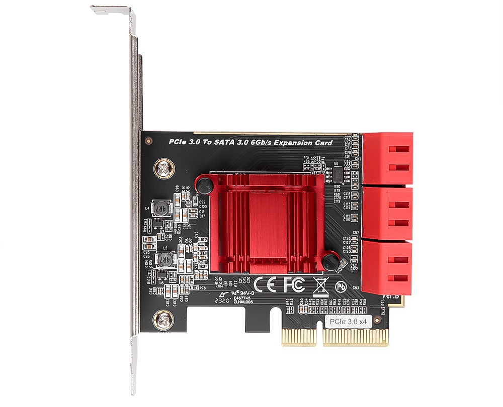
Despite what the silk screen on the PCB states, it is not “PCIe 3.0 x4” except in PCIe slot dimensions (since there is no standard for a physical PCIe x2 connector). The ASM1166 has a PCIe 3.0 x2 interface:

So the ASM1166 cannot provide full bandwidth to six SATA3 devices, but it is not as bandwidth limited as other SATA controllers which have only a PCIe x1 host connection. Be aware that the bandwidth will be halved if you install it in a PCIe 2.0 slot, due to the less efficient encoding of PCIe 2.0 (8b/10b) versus PCIe 3.0 (128b/130b).

The board designer did properly route the PCIe x2 connection to the host, as confirmed by lspci:

02:00.0 SATA controller: ASMedia Technology Inc. Device 1166 (rev 02) (prog-if 01 [AHCI 1.0])
        Subsystem: ZyDAS Technology Corp. Device 2116
        Physical Slot: 3
        Control: I/O+ Mem+ BusMaster+ SpecCycle- MemWINV- VGASnoop- ParErr+ Stepping- SERR+ FastB2B- DisINTx+
        Status: Cap+ 66MHz- UDF- FastB2B- ParErr- DEVSEL=fast >TAbort- <TAbort- <MAbort- >SERR- <PERR- INTx-
        Latency: 0, Cache Line Size: 64 bytes
        Interrupt: pin A routed to IRQ 26
        Region 0: Memory at f7a82000 (32-bit, non-prefetchable) [size=8K]
        Region 5: Memory at f7a80000 (32-bit, non-prefetchable) [size=8K]
        Expansion ROM at f7a00000 [disabled] [size=512K]
        Capabilities: [40] Power Management version 3
                Flags: PMEClk- DSI+ D1- D2- AuxCurrent=0mA PME(D0+,D1-,D2-,D3hot+,D3cold+)
                Status: D0 NoSoftRst- PME-Enable- DSel=0 DScale=0 PME-
        Capabilities: [50] MSI: Enable+ Count=1/1 Maskable- 64bit+
                Address: 00000000fee00298  Data: 0000
        Capabilities: [80] Express (v2) Endpoint, MSI 00
                DevCap: MaxPayload 512 bytes, PhantFunc 0, Latency L0s <64ns, L1 <1us
                        ExtTag+ AttnBtn- AttnInd- PwrInd- RBE+ FLReset- SlotPowerLimit 75.000W
                DevCtl: CorrErr+ NonFatalErr+ FatalErr+ UnsupReq-
                        RlxdOrd- ExtTag+ PhantFunc- AuxPwr- NoSnoop+
                        MaxPayload 128 bytes, MaxReadReq 512 bytes
                DevSta: CorrErr- NonFatalErr- FatalErr- UnsupReq- AuxPwr- TransPend-
                LnkCap: Port #0, Speed 8GT/s, Width x2, ASPM L0s L1, Exit Latency L0s <4us, L1 <64us
                        ClockPM+ Surprise- LLActRep- BwNot- ASPMOptComp+
                LnkCtl: ASPM Disabled; RCB 64 bytes Disabled- CommClk+
                        ExtSynch- ClockPM- AutWidDis- BWInt- AutBWInt-
                LnkSta: Speed 8GT/s (ok), Width x2 (ok)
                        TrErr- Train- SlotClk+ DLActive- BWMgmt- ABWMgmt-
                DevCap2: Completion Timeout: Not Supported, TimeoutDis-, NROPrPrP-, LTR-
                         10BitTagComp-, 10BitTagReq-, OBFF Not Supported, ExtFmt-, EETLPPrefix-
                         EmergencyPowerReduction Not Supported, EmergencyPowerReductionInit-
                         FRS-, TPHComp-, ExtTPHComp-
                         AtomicOpsCap: 32bit- 64bit- 128bitCAS-
                DevCtl2: Completion Timeout: 50us to 50ms, TimeoutDis-, LTR-, OBFF Disabled
                         AtomicOpsCtl: ReqEn-
                LnkCtl2: Target Link Speed: 8GT/s, EnterCompliance- SpeedDis-
                         Transmit Margin: Normal Operating Range, EnterModifiedCompliance- ComplianceSOS-
                         Compliance De-emphasis: -6dB
                LnkSta2: Current De-emphasis Level: -3.5dB, EqualizationComplete+, EqualizationPhase1+
                         EqualizationPhase2+, EqualizationPhase3+, LinkEqualizationRequest-
        Capabilities: [100 v1] Advanced Error Reporting
                UESta:  DLP- SDES- TLP- FCP- CmpltTO- CmpltAbrt- UnxCmplt- RxOF- MalfTLP- ECRC- UnsupReq- ACSViol-
                UEMsk:  DLP- SDES- TLP- FCP- CmpltTO- CmpltAbrt- UnxCmplt- RxOF- MalfTLP- ECRC- UnsupReq+ ACSViol-
                UESvrt: DLP+ SDES+ TLP- FCP+ CmpltTO- CmpltAbrt- UnxCmplt- RxOF+ MalfTLP+ ECRC- UnsupReq- ACSViol-
                CESta:  RxErr- BadTLP- BadDLLP- Rollover- Timeout- AdvNonFatalErr-
                CEMsk:  RxErr- BadTLP- BadDLLP- Rollover- Timeout- AdvNonFatalErr+
                AERCap: First Error Pointer: 00, ECRCGenCap- ECRCGenEn- ECRCChkCap- ECRCChkEn-
                        MultHdrRecCap- MultHdrRecEn- TLPPfxPres- HdrLogCap-
                HeaderLog: 00000000 00000000 00000000 00000000
        Capabilities: [130 v1] Secondary PCI Express
                LnkCtl3: LnkEquIntrruptEn-, PerformEqu-
                LaneErrStat: 0
        Kernel driver in use: ahci

Power consumption is very good, with the card installed system power consumption was 2.8W higher.

PCIe SATA controllers based on the ASM1166 are comparatively priced to other 5-6 port SATA controllers, but offer more bandwidth than cards using the JMicron JMB585 or Marvell 88SE9125. ASM1166 controllers can be found for around 20€ on AliExpress. There are seemingly some sellers shipping cards with PCIe x1 connectors, so I would advise you to check the reviews of other customers to see which variant the seller sends.


I was unable to find detailed information about the card such as power consumption and lspci output online, which I find very useful when making purchasing decisions, so I thought I should write a short summary. This is not a review or endorsement of any online marketplace or brand.


(The following section was added in March 2023)

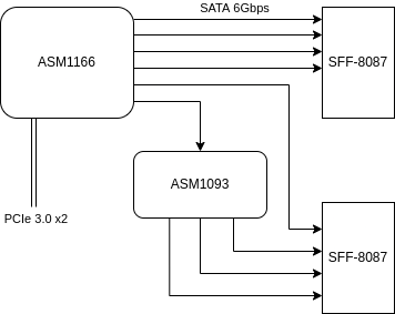
Some sellers are offering an 8-port version of the card (SA3028S) with two SFF-8087 connectors for around 35€ on AliExpress (incl. VAT, S&H to Europe). Given that the ASM1166 is a 6-port SATA controller, I bought one to see if it was just the ASM1166 with a SATA port multiplier (spoiler: yes; via the ASM1093).

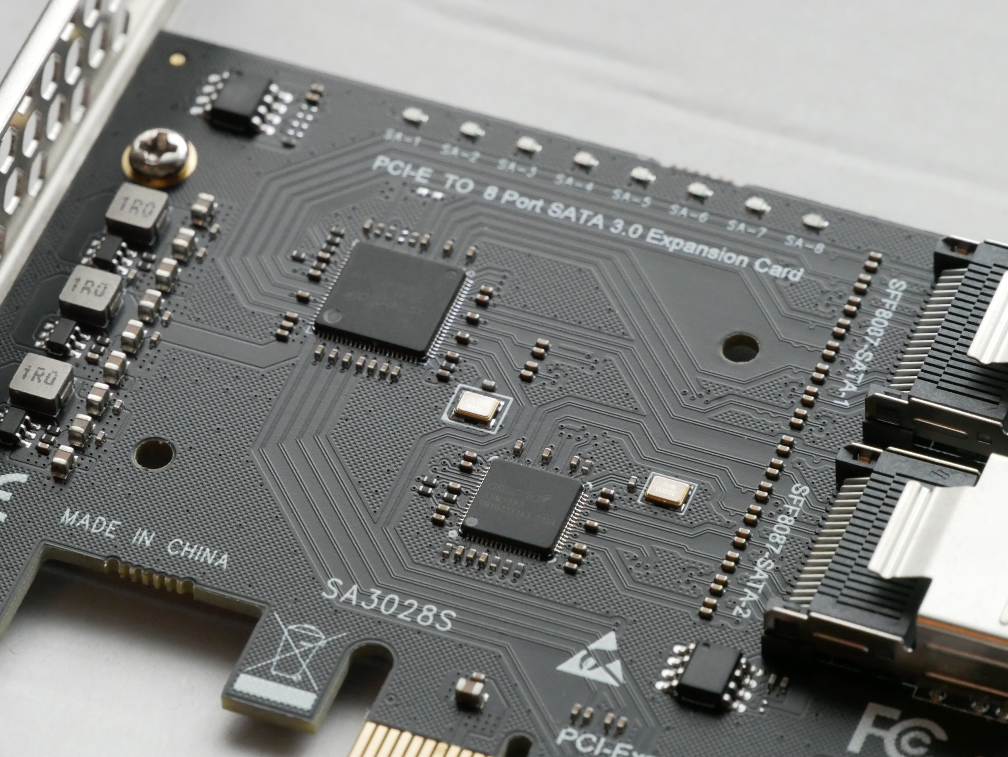
SA3028S SATA controller with the heat sink removed, showing the ASM1166 and ASM1093

Ports 6, 7, and 8 are connected to the ASM1093 port multiplier, which is connected to port 6 of the ASM1166. This is hardly an issue for HDDs, since the sequential throughput is typically well below 6Gbps, however if you are using SSDs with the controller, then you will notice the reduced bandwidth on ports 6-8.

Random observation: the board is entirely powered from +3.3VDC, it does not use the +12VDC rail at all.

Fujitsu TX140 S2

The SuperMicro X10SLE-F is nice, but it has very limited expansion; no PCIe slots and the MicroLP adapters with SFP+ are insanely expensive. Fujitsu motherboards, in the EU, are quite cheap (33€ on eBay) and I have never owned a Fujitsu system before, so I thought I would give it a try.

Fujitsu TX140 S2 motherboard

The first order of business, since I bought a bare motherboard, is to power it from an ATX power supply. Luckily for me, other people have determined the 16-pin power supply pinout:

Fujitsu 16-pin power supply pinout

Side note: this appears to be a common power supply connector for Fujitsu motherboards with a 16-pin power connector. The Celsius W520 uses the same pinout.

The 12V rail appears to go directly to the PCIe slots and is completely isolated from 12V V1.


If the ambient temperature sensor is absent, iRMC considers the system in an error state. The Global Error/CSS lights are flashing and the fans run at full speed (100% PWM).

Unfortunately the ambient temperature sensor is integrated into the front-panel assembly (c26361-k644-c550), which I don’t have:

I couldn’t locate the technical manual for the TX140 S2 (D3239), but technical manual of the TX140 S1 (D3049) has the following to say:

Measurement of the processor and the system internal temperature by an onboard temperature sensor, measurement of the ambient temperature by a I²C temperature sensor.

System board D3049 for PRIMERGY TX140 S1 / TX120 S3 – Technical Manual

I am unaware of any publicly available pinout of the 16 pin front-panel header (2×8, 2.0mm spacing), so I reverse engineered it:

Fujitsu TX140 S2 front panel pinout

In table format:

PinDescriptionPinDescription
1SDA (serial data)23.3V
3Ground4SCL (serial clock)
5CSS LED positive (Customer self service)6ID button
7ID LED+ (anode)8NMI button
9Reset button10Global Error LED+ (anode)
11Ground12HDD activity LED+ (anode)
13Standby LED+ (anode)14Power LED+ (anode)
15Power button16Key (pin absent)
Fujitsu TX140 S2 front panel pinout

We can confirm the I²C pins with a logic analyzer:

I²C found

Now unfortunately, there are no high resolution photos of the front-panel PCB, so it’s not possible to easily determine which I²C temperature sensor is being used.

There is a photo of a Fujitsu RX300 front-panel with a failed temperature sensor, but that is only enough to allow us to guess the chip model as the Texas Instruments LM75.

The CJMCU-75 is a cheap and readily available LM75 sensor

We can also guess the I²C address from the RX300 front-panel: all 3 address lines should be tied to VCC.

Now with the sensor connected to the front-panel connector using the pinout above, it is time to find out if Fujitsu used the same ambient temperature sensor on the RX300 and TX140 S2, and if I guessed the I2C address correctly.

Yes, iRMC S4 reads the ambient temperature from the CJMCU LM75!

There is a chassis IDPROM also in the front panel assembly, which from the iRMC log appears to store a backup of the BIOS parameters after successful POST. I consider the IDPROM somewhat optional, as iRMC does not consider it a critical component in terms of server functionality.


First impressions are good, power consumption is very low, though not as low as the X10SLE-F. Idle power consumption in Linux is under 20W with an E3-1220 v3 and 16GB of PC3L-12800E.

lspci output:

00:00.0 Host bridge: Intel Corporation Xeon E3-1200 v3 Processor DRAM Controller (rev 06)
00:01.0 PCI bridge: Intel Corporation Xeon E3-1200 v3/4th Gen Core Processor PCI Express x16 Controller (rev 06)
00:01.1 PCI bridge: Intel Corporation Xeon E3-1200 v3/4th Gen Core Processor PCI Express x8 Controller (rev 06)
00:14.0 USB controller: Intel Corporation 8 Series/C220 Series Chipset Family USB xHCI (rev 05)
00:19.0 Ethernet controller: Intel Corporation Ethernet Connection I217-LM (rev 05)
00:1a.0 USB controller: Intel Corporation 8 Series/C220 Series Chipset Family USB EHCI #2 (rev 05)
00:1c.0 PCI bridge: Intel Corporation 8 Series/C220 Series Chipset Family PCI Express Root Port #1 (rev d5)
00:1c.2 PCI bridge: Intel Corporation 8 Series/C220 Series Chipset Family PCI Express Root Port #3 (rev d5)
00:1d.0 USB controller: Intel Corporation 8 Series/C220 Series Chipset Family USB EHCI #1 (rev 05)
00:1f.0 ISA bridge: Intel Corporation C224 Series Chipset Family Server Standard SKU LPC Controller (rev 05)
00:1f.2 SATA controller: Intel Corporation 8 Series/C220 Series Chipset Family 6-port SATA Controller 1 [AHCI mode] (rev 05)
00:1f.3 SMBus: Intel Corporation 8 Series/C220 Series Chipset Family SMBus Controller (rev 05)
00:1f.6 Signal processing controller: Intel Corporation 8 Series Chipset Family Thermal Management Controller (rev 05)
03:00.0 VGA compatible controller: Matrox Electronics Systems Ltd. MGA G200e [Pilot] ServerEngines (SEP1) (rev 05)
03:00.1 Co-processor: Emulex Corporation ServerView iRMC HTI
04:00.0 Ethernet controller: Intel Corporation I210 Gigabit Network Connection (rev 03)

I have requested the GPL source code of iRMC from Fujitsu, and if they get back to me with the source code I may have some interesting findings to share. Stay tuned…