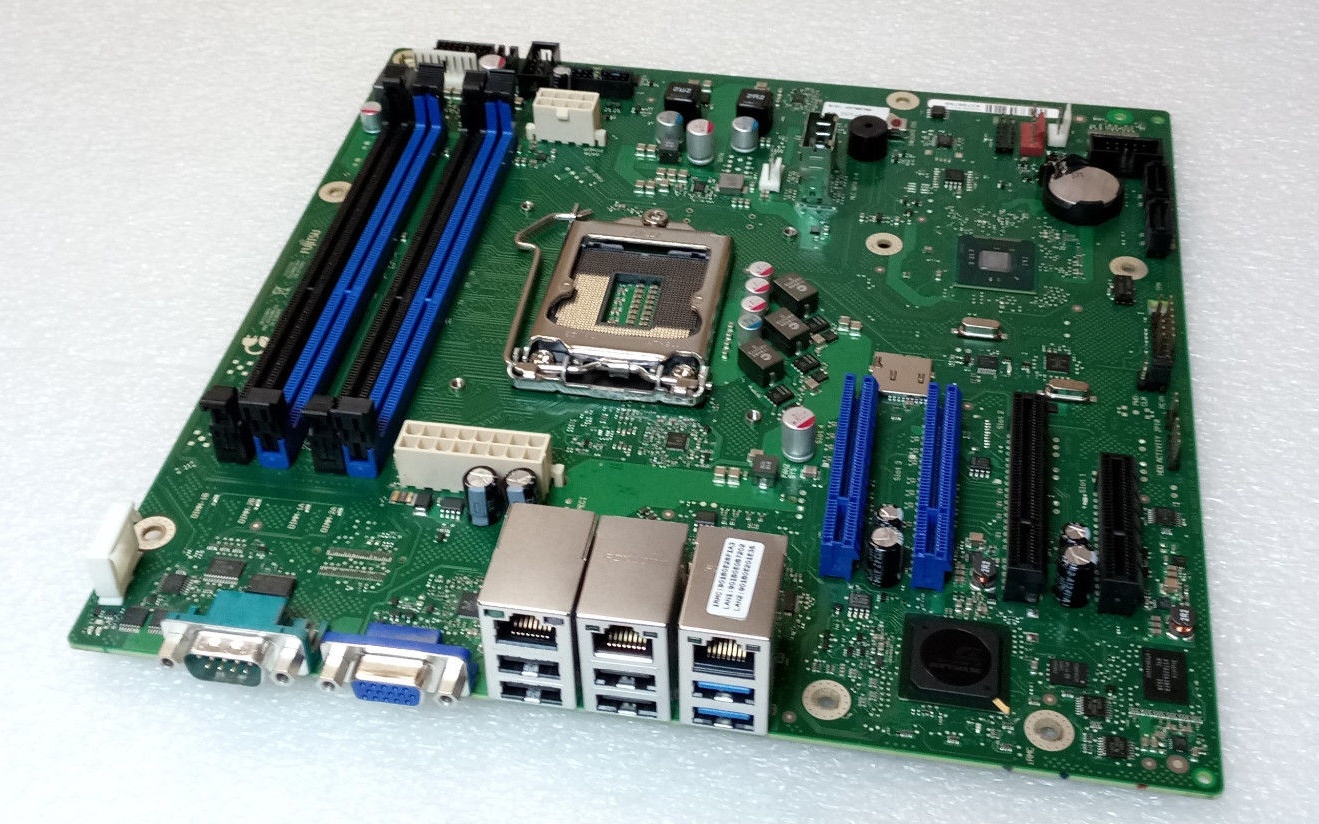
The SuperMicro X10SLE-F is nice, but it has very limited expansion; no PCIe slots and the MicroLP adapters with SFP+ are insanely expensive. Fujitsu motherboards, in the EU, are quite cheap (33€ on eBay) and I have never owned a Fujitsu system before, so I thought I would give it a try.
The first order of business, since I bought a bare motherboard, is to power it from an ATX power supply. Luckily for me, other people have determined the 16-pin power supply pinout:
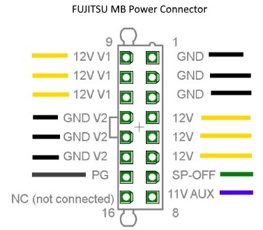
Side note: this appears to be a common power supply connector for Fujitsu motherboards with a 16-pin power connector. The Celsius W520 uses the same pinout.
The 12V rail appears to go directly to the PCIe slots and is completely isolated from 12V V1.
If the ambient temperature sensor is absent, iRMC considers the system in an error state. The Global Error/CSS lights are flashing and the fans run at full speed (100% PWM).
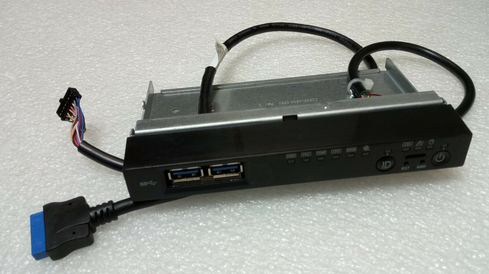
Unfortunately the ambient temperature sensor is integrated into the front-panel assembly (c26361-k644-c550), which I don’t have:
I couldn’t locate the technical manual for the TX140 S2 (D3239), but technical manual of the TX140 S1 (D3049) has the following to say:
Measurement of the processor and the system internal temperature by an onboard temperature sensor, measurement of the ambient temperature by a I²C temperature sensor.
System board D3049 for PRIMERGY TX140 S1 / TX120 S3 – Technical Manual
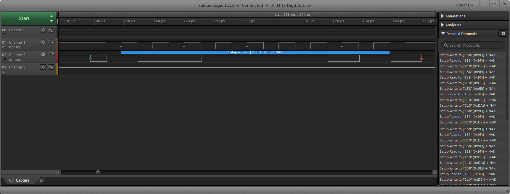
I am unaware of any publicly available pinout of the 16 pin front-panel header (2×8, 2.0mm spacing), so I reverse engineered it:
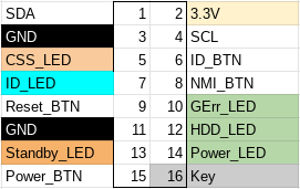
In table format:
| Pin | Description | Pin | Description |
|---|---|---|---|
| 1 | SDA (serial data) | 2 | 3.3V |
| 3 | Ground | 4 | SCL (serial clock) |
| 5 | CSS LED positive (Customer self service) | 6 | ID button |
| 7 | ID LED+ (anode) | 8 | NMI button |
| 9 | Reset button | 10 | Global Error LED+ (anode) |
| 11 | Ground | 12 | HDD activity LED+ (anode) |
| 13 | Standby LED+ (anode) | 14 | Power LED+ (anode) |
| 15 | Power button | 16 | Key (pin absent) |
We can confirm the I²C pins with a logic analyzer:
Now unfortunately, there are no high resolution photos of the front-panel PCB, so it’s not possible to easily determine which I²C temperature sensor is being used.
There is a photo of a Fujitsu RX300 front-panel with a failed temperature sensor, but that is only enough to allow us to guess the chip model as the Texas Instruments LM75.
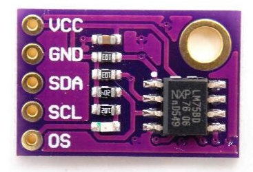
We can also guess the I²C address from the RX300 front-panel: all 3 address lines should be tied to VCC.
Now with the sensor connected to the front-panel connector using the pinout above, it is time to find out if Fujitsu used the same ambient temperature sensor on the RX300 and TX140 S2, and if I guessed the I2C address correctly.
There is a chassis IDPROM also in the front panel assembly, which from the iRMC log appears to store a backup of the BIOS parameters after successful POST. I consider the IDPROM somewhat optional, as iRMC does not consider it a critical component in terms of server functionality.
First impressions are good, power consumption is very low, though not as low as the X10SLE-F. Idle power consumption in Linux is under 20W with an E3-1220 v3 and 16GB of PC3L-12800E.
lspci output:
00:00.0 Host bridge: Intel Corporation Xeon E3-1200 v3 Processor DRAM Controller (rev 06)
00:01.0 PCI bridge: Intel Corporation Xeon E3-1200 v3/4th Gen Core Processor PCI Express x16 Controller (rev 06)
00:01.1 PCI bridge: Intel Corporation Xeon E3-1200 v3/4th Gen Core Processor PCI Express x8 Controller (rev 06)
00:14.0 USB controller: Intel Corporation 8 Series/C220 Series Chipset Family USB xHCI (rev 05)
00:19.0 Ethernet controller: Intel Corporation Ethernet Connection I217-LM (rev 05)
00:1a.0 USB controller: Intel Corporation 8 Series/C220 Series Chipset Family USB EHCI #2 (rev 05)
00:1c.0 PCI bridge: Intel Corporation 8 Series/C220 Series Chipset Family PCI Express Root Port #1 (rev d5)
00:1c.2 PCI bridge: Intel Corporation 8 Series/C220 Series Chipset Family PCI Express Root Port #3 (rev d5)
00:1d.0 USB controller: Intel Corporation 8 Series/C220 Series Chipset Family USB EHCI #1 (rev 05)
00:1f.0 ISA bridge: Intel Corporation C224 Series Chipset Family Server Standard SKU LPC Controller (rev 05)
00:1f.2 SATA controller: Intel Corporation 8 Series/C220 Series Chipset Family 6-port SATA Controller 1 [AHCI mode] (rev 05)
00:1f.3 SMBus: Intel Corporation 8 Series/C220 Series Chipset Family SMBus Controller (rev 05)
00:1f.6 Signal processing controller: Intel Corporation 8 Series Chipset Family Thermal Management Controller (rev 05)
03:00.0 VGA compatible controller: Matrox Electronics Systems Ltd. MGA G200e [Pilot] ServerEngines (SEP1) (rev 05)
03:00.1 Co-processor: Emulex Corporation ServerView iRMC HTI
04:00.0 Ethernet controller: Intel Corporation I210 Gigabit Network Connection (rev 03)
I have requested the GPL source code of iRMC from Fujitsu, and if they get back to me with the source code I may have some interesting findings to share. Stay tuned…
What about the power consumption (idle) in comparison to the Supermicro X10 board?
Power consumption at the wall is 18.6W idle, and with the powertop suggested tuning it drops to 18.2W. This is with two Gigabit Ethernet connections (1 to iRMC, 1 to i210 NIC)
This is a few watts more than the SuperMicro X10, however for that measurement I took the power consumption value from the BMC management interface, not measured from the wall. I would estimate the AC consumption of the X10SLE-F to be around 15W (Dell DA-2 power supply has a little overhead).
Power consumption while off is around 6.5W with iRMC S4 booted. This is roughly the same as the X10SLE-F.
In my opinion, 3W difference is worth it considering how much more IO you get from the TX140 S2 motherboard.
What a relief! Thanks for sharing the info regarding the LM75. I just put one in my TX150 S7 and instantly it went silent.
I’d wish I had done some investigation before I went out and bought the motherboard for my Vyos switch machine…
Finding out afterwards that it needs proprietary power is annoying, but I went out and bought myself a fitting powersupply.
Finding out later that there are no standard specifications for powering a sata drive, but I went out and bought myself a fitting cable.
Then ultimately finding out what you describe in this article that the ambient sensor needs data, before allowing the board to power on…
All in all, wanting to get a board with remote kvm, which this currently doesn’t even have, only web based fujitsu stuff (Hopefully a BIOS update fixes that) for cheap, turned into a long lasting adventure, which wasn’t as cheap as getting a supermicro equivalent in the bitter end 😀
Thanks for your article, and I hope that people who are about to make the same mistake as I have, will read this and have one extra think about their project 🙂
It’s quite easy to modify a 24 pin ATX extension cable to the Fujitsu pinout. The only “complicated” part is that you need a DC-DC step up for 5VSB to 11VSB.
The SATA power connector is the same physical connector as an ATX EPS (5557 2×4), so you can just buy an EPS extension cable and hack it to SATA power. I will update the article with the pinout.
I would say in total the extension cables, voltage adapter, and sensor should cost you less than 15€.
If you are not experienced in soldering components, then this motherboard is a poor choice, because it is not plug and play with standard components.
No, the board will power on without the sensor present. It will just indicate a fault and run the fans at 100% duty cycle.
I am waiting for Fujitsu to respond to my GPL request for the iRMC OS, but in the mean time I have a solution for remote KVM. The email address you provided is invalid, so please email me and I can give you more details 😉
Hey, i have recently acquired PRIMERGY TX1320 M3 on iRMC S4 for my home lab, could you please share the KVM solution if You still have it?
Of course, I will contact you directly about this 🙂
Hi, i just moved the D3239 board from my TX140 S2 to a spare TX1320 M3 SFF case, and was surprised that the front panels are compatible. Know my TX140 think’s it’s a TX1320 😀
If you need any details on the front panel of the TX140 S2, i got mine here on the desk. So just ask!
Got a logic analyzer somewhere, and a Hantek DSO, if requiered.
And I would love to hear about your solution regarding KVM, my other server (another TX1320 M3 also has iRMC S4, but without usable KVM).
Hi Tim, thanks for volunteering to probe the TX140 S2 front panel! I sent you an email with my request.
Hi Tim! Maybe you still have a front panel from TX140 S2 or you have photo with readable IC’s marking and board traces? I’m found and download a Chassis ID Tool and want to make experiment with IDPROM.
Hi, thank you for this post. I’m not very familiar with sensors, and would like to get a confirmation on the wiring you did to get the CJMCU-75 to work. So solder all the address lines to VCC on the back and connect the VCC to 3.3v, SDA and SCL to their respective pins and ground to ground, OS remaining unconnected? Sorry for a such a simple question, trying to avoid frying my one temperature sensor and waiting weeks for another one (always buy two).
It appears I forgot to take a photo of the back of the sensor, and it is heat shrinked and installed in the chassis now.
Yes, I recall bridging VCC to each address line on the back of the CJMCU-75. I connected VCC (3.3V), SDA, SCL, and GND. OS is not connected.
Hi, i have purchased a TX1330 M2 board (D3373-A11 GS2), not realizing what a mistake i made until i have found your post. Anyways, I have a 24pin to 16pin ATX power adapter from aliexpress, a CJMCU-75 (not yet connected) and a supermicro case where all is supposed to go into. I have tried to connect the front panel connector with dupont wires – connected just what seems to be power button and the power LED.
I was trying to turn on the system, but to no avail. LEDs light up, from what i can see the following:
– GEL LED flashing orange (indicating some serious error)
– iRMC flashing green (should mean operational)
– AUX power LED solid yellow (AUX voltages within range)
System fans are not running, power LED is blinking for a short time (so i guess its correctly connected), then has a faint solid light. Power button does not seem to do anything (tried holding it, but the server did not turn off), so i guess its not connected properly.
iRMC ethernet port does not seem to do anything, and there is no video output. Do you have any ideas for troubleshooting?
Hello
i just bought the same board for my home server project. Did you resolve your problems or is there a way you could help me/tell me what u did?