Tag Archives: fujitsu

Fujitsu TX1320 M3

As with many purchases, this one began with a thread on ServeTheHome. Given my previous work on the Fujitsu TX140 S2 motherboard, how could I refuse the offer of a barebones Fujitsu TX1320 M3 for only 29€?

Fujitsu TX1320 M3

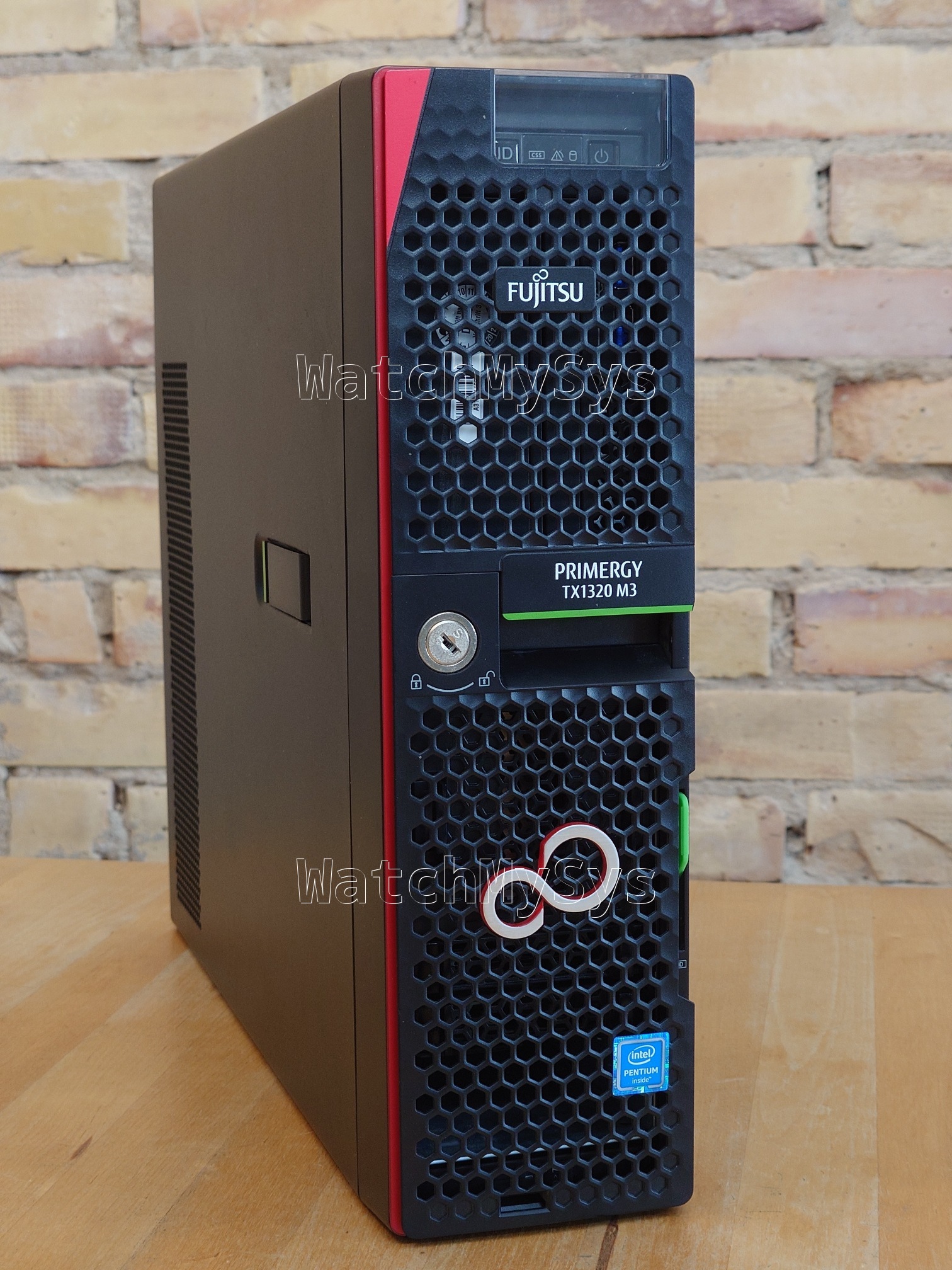
The TX1320 M3 is slightly too tall to fit within 2U, measuring at 398x340x98mm. Those wishing to place it on a rack shelf, you will need to budget 2.5U for the unit.


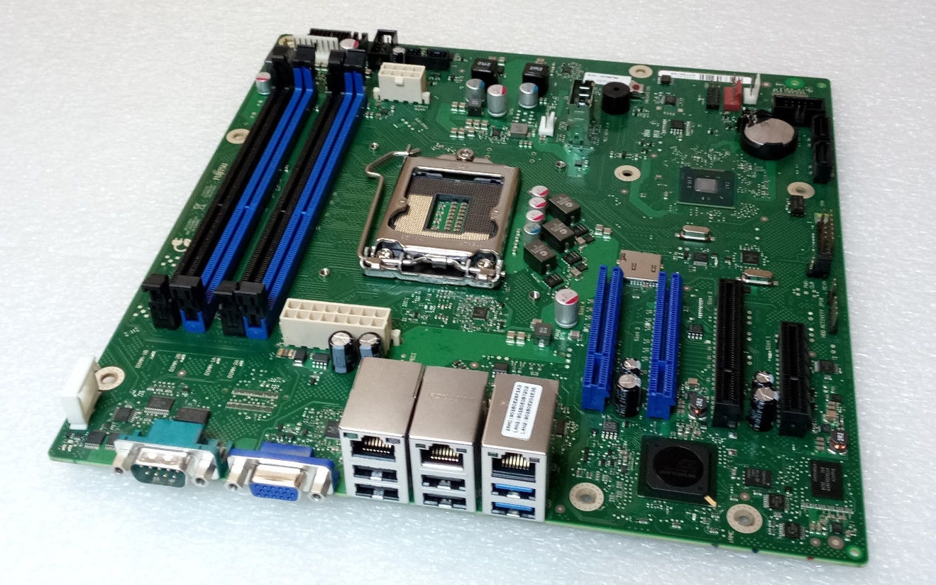
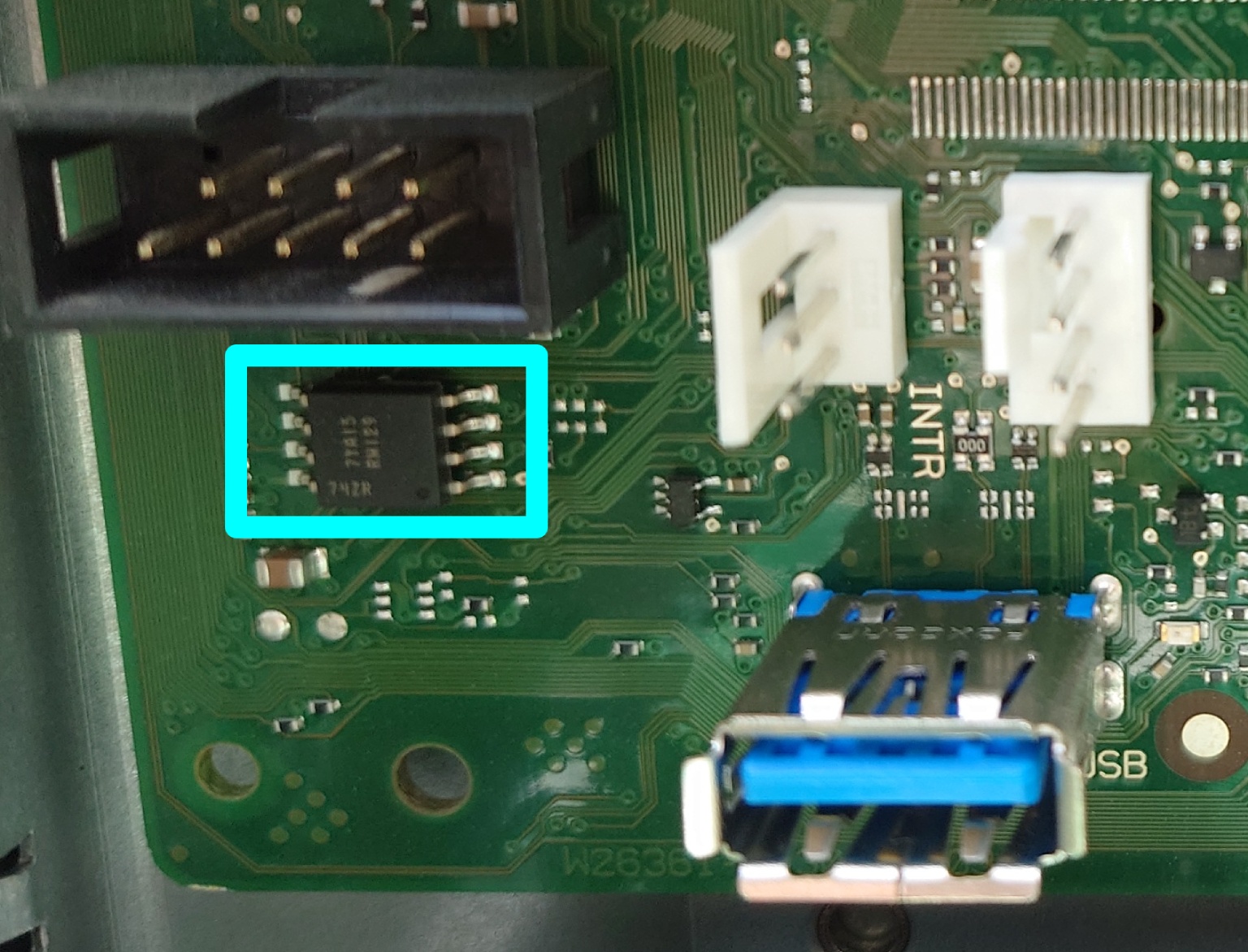
My TX1320 M3 came with BIOS 1.19.0, which does not support Xeon v5 CPUs. Not knowing the iRMC S4 password, it was not possible to flash a newer BIOS via iRMC. But, the SOIC8 that contains the BIOS was easily located (on the front of the motherboard, near to the INTR header and internal USB3 port).

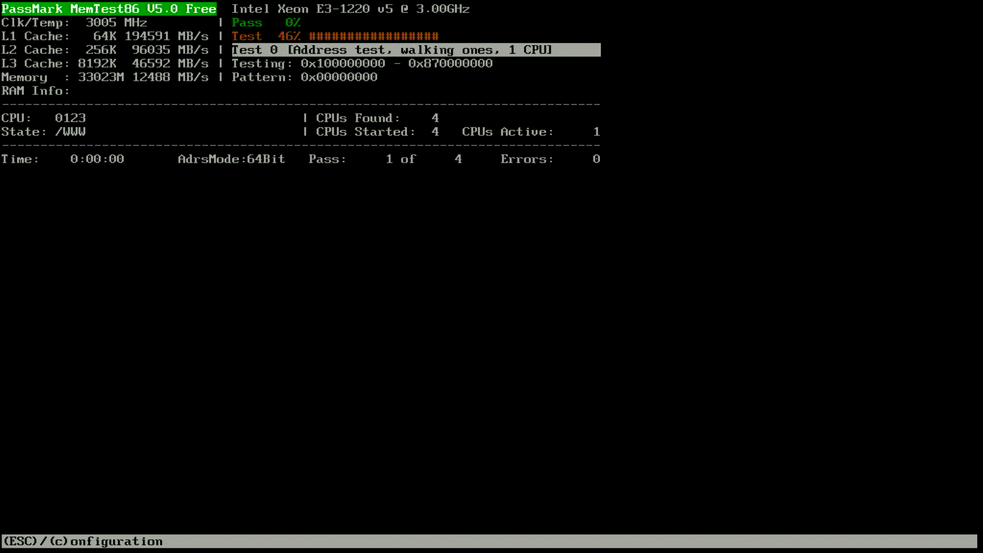
The BIOS update D3373-B1.ROM file provided by Fujitsu is exactly 8388608 bytes. So, updating the BIOS requires only a ch341a programmer and a SOIC8 chip-clip. Dump the current BIOS, replace the last 8MB with D3373-B1.ROM downloaded from Fujitsu, and reflash to have support for a Xeon v5 CPU:

$ sudo flashrom -p ch341a_spi -c "N25Q128..3E" -r TX1320.bin
$ dd if=D3373-B1.ROM of=TX1320.bin bs=1M seek=8
$ sudo flashrom -p ch341a_spi -c "N25Q128..3E" -w TX1320.bin

After booting Linux, it is easy to reset the iRMC S4 password using ipmitool.


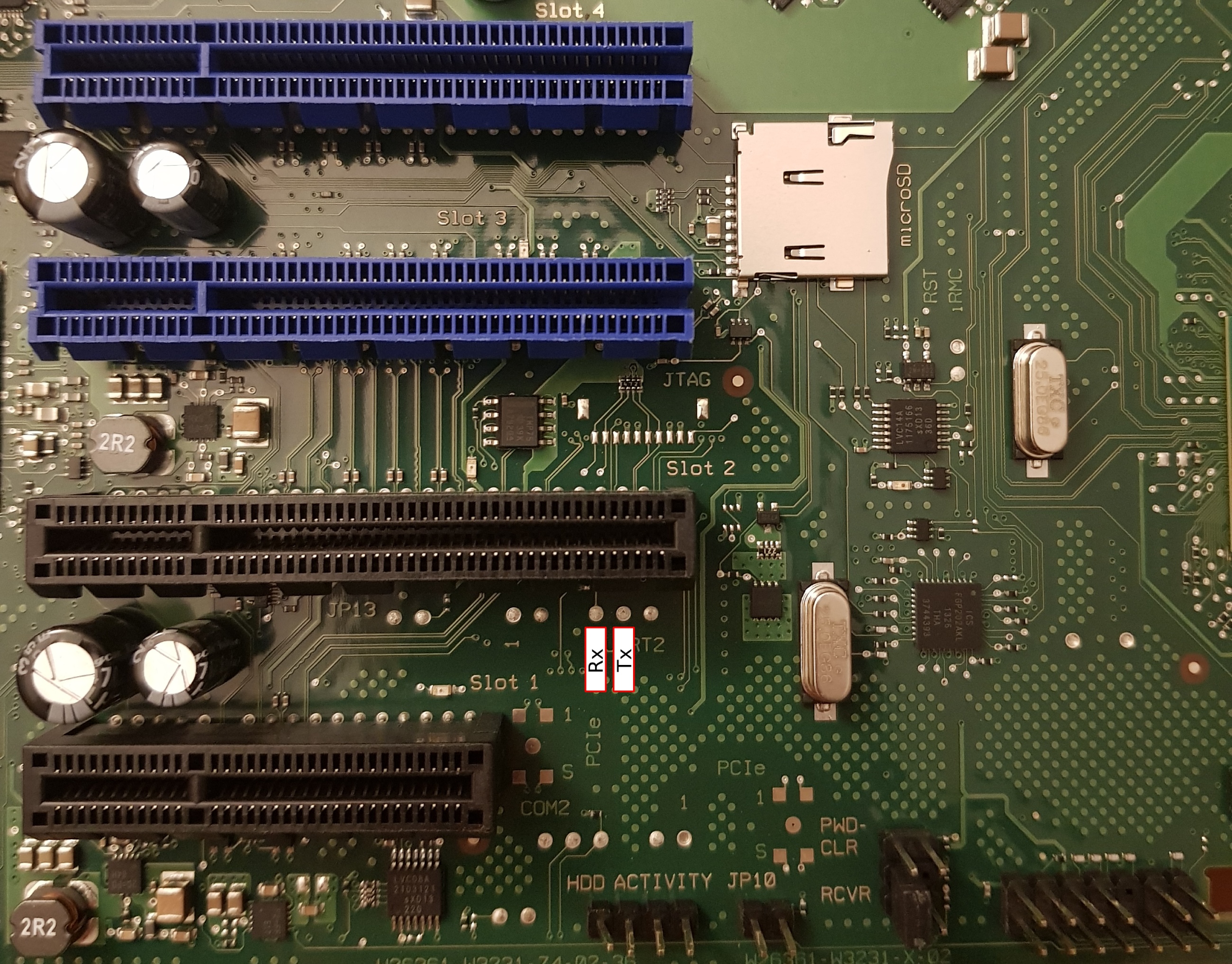
iRMC S4 on the TX1320 M3 motherboard has the UART routed to an unpopulated header and has the same parameters as the TX140 S2: 38400n8.

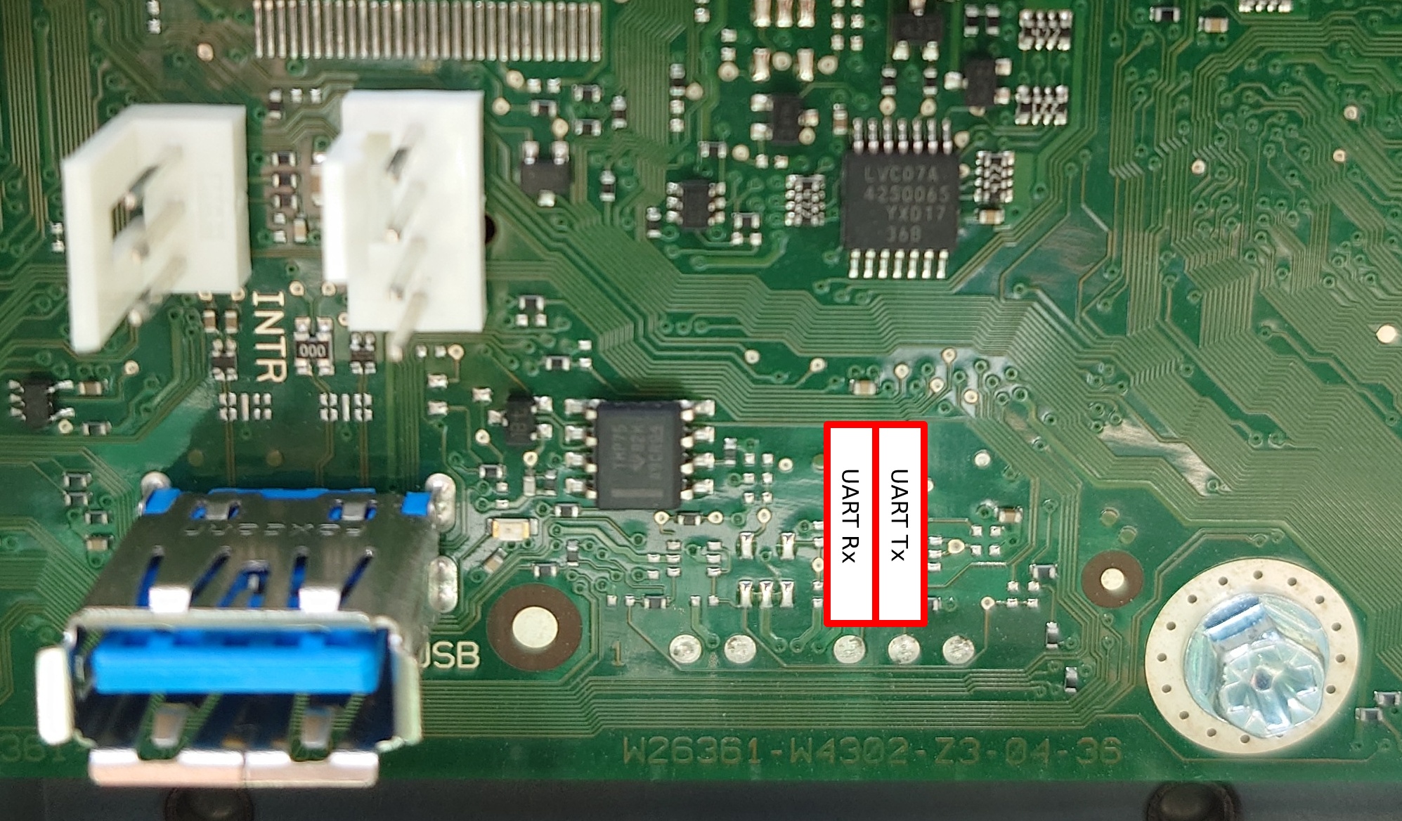
The pin beside UART Tx is not a ground, it’s a GPIO from the Pilot III. Pin 3 of the INTR header (closest to the USB port) is GND and fits a 2.54mm prototype wire. The iRMC S4 bootlog is available in this gist.

UART access does not instantly make you god of iRMC S4. After booting, remmman is running on the uart, so without knowing a valid username and password, you can’t gain access. u-boot is built with the dhcp and tftpboot commands, so you could potentially boot a modified image from the network that would give you root access (untested).

The GPL components of iRMC S4 are available on GitHub.


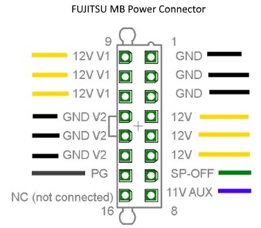
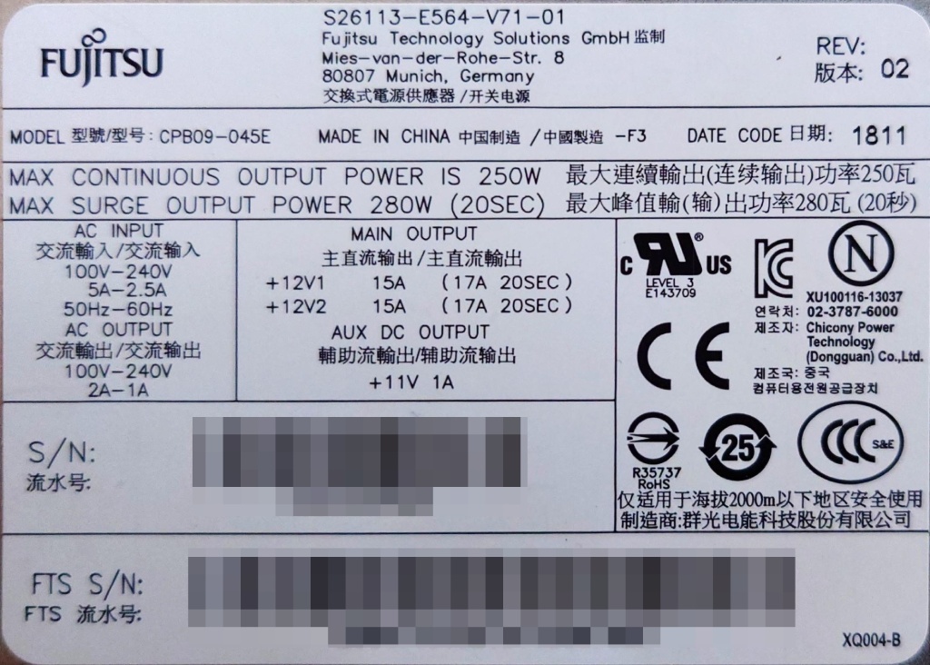
The Fujitsu 250W power supply (Model: CPB09-045E, S26113-E564-V71-01) has the dimensions 93x71x187mm, which should allow for the installation of a TFX PSU (85x65x175mm) in the chassis with minimal modification. Being a Fujitsu workstation, the power supply pin-out is identical to the TX140 S2.

The SATA power connector on the motherboard is a Molex 5559 2×4 with the following pinout (top view, looking toward PCB):

GND* 5V GND 12V*
GND* 5V* GND* 12V*

The 2.5″ backplane (Fujitsu P/N: A3C40176096) has a Molex 5559 2×2 power connector with the following pinout (top view, looking toward PCB):

GND GND*
12V 12V*

Note that only the the conductors marked with * are populated in the Fujitsu wiring harness.


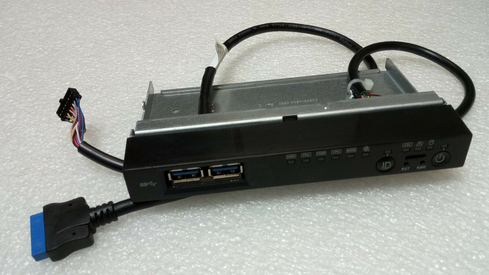
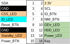
The 16 pin front-panel header has the same pinout as the TX140 S2:

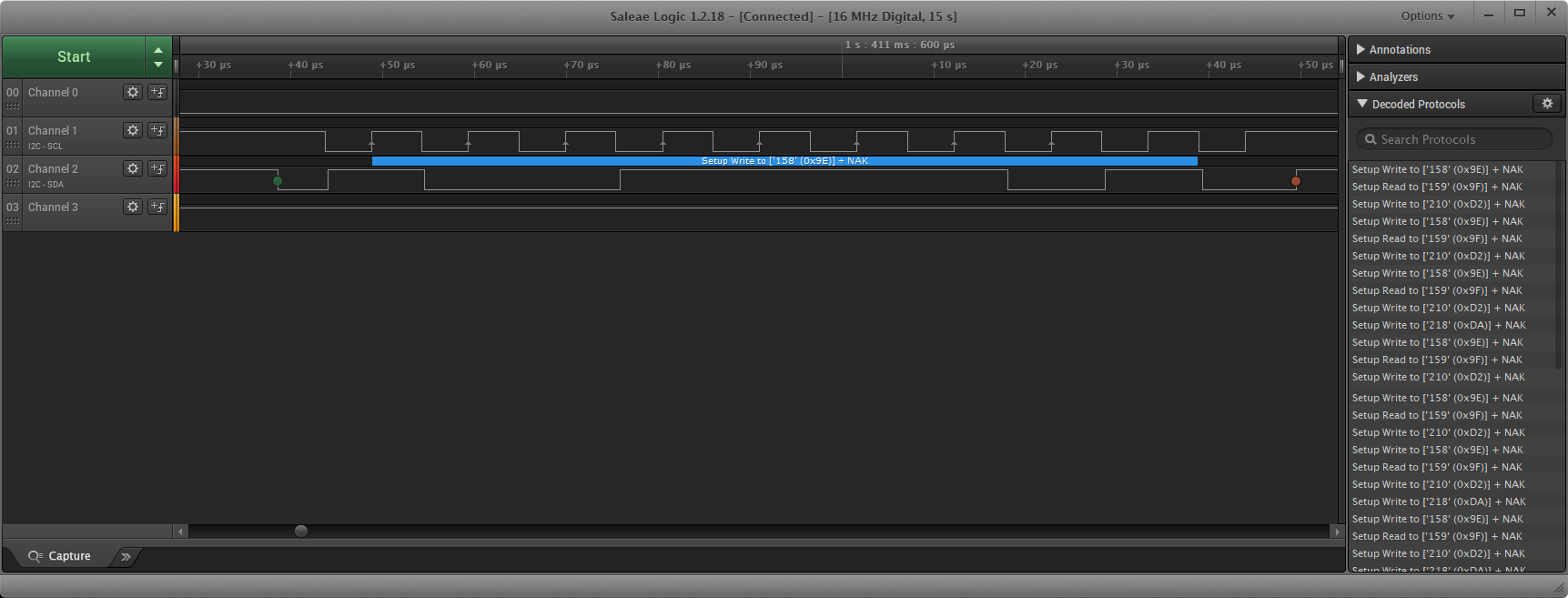
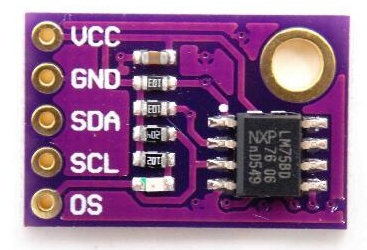
As expected, we find two I2C EEPROMs (TSSOP8) and a Texas Instruments LM75 temperature sensor (VSSOP8) on the front-panel PCB (Fujitsu P/N: A3C40167342).

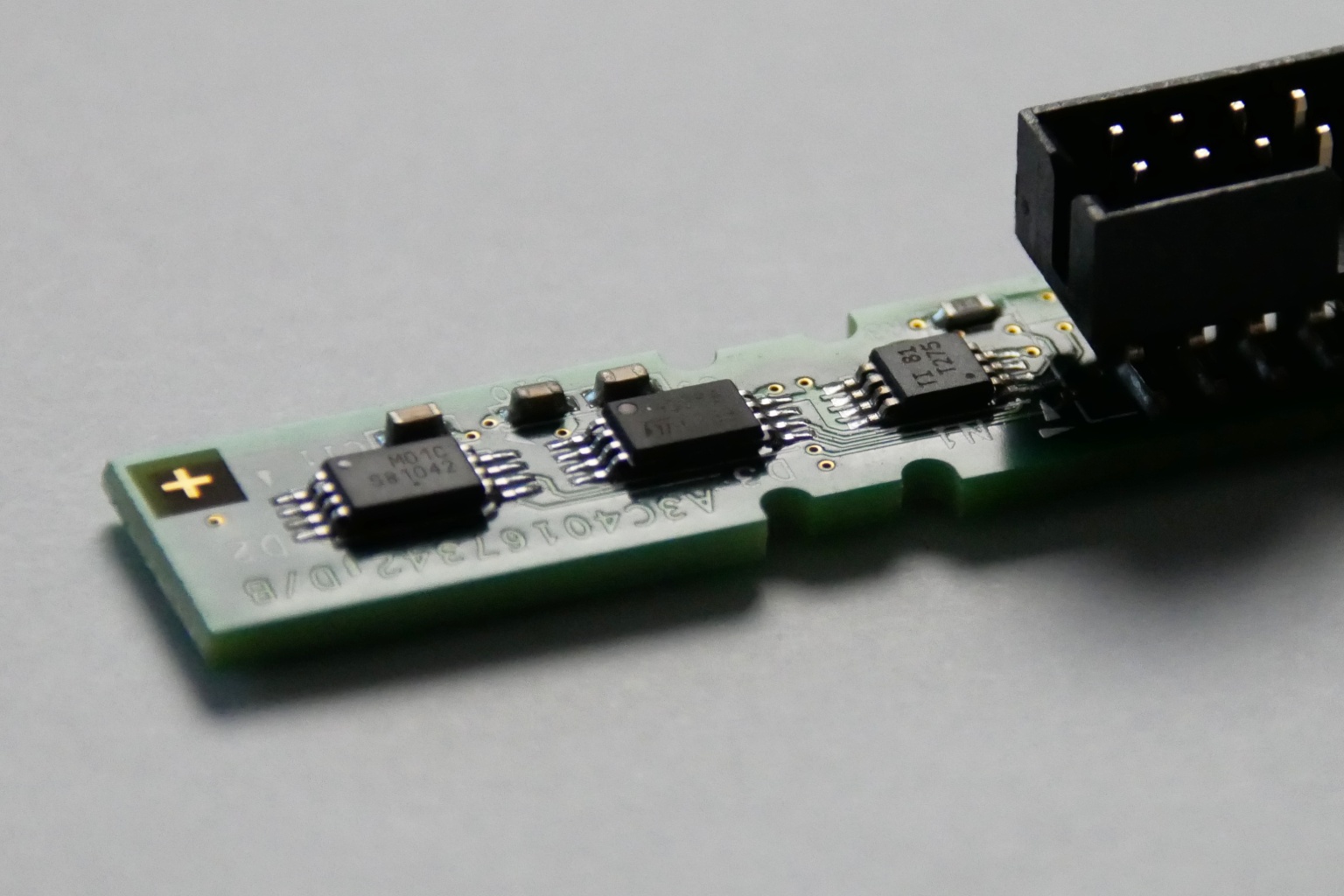
TX1320 M3 front-panel PCB


The TX1320 M3 noise profile is excellent, it is slightly audible during POST, but inaudible once booted into the OS (Linux).

The CPU cooler (V26898-B1003-V1/A3C40175673/A3C40175674) is a small dual heat pipe design with two towers with a fan (Delta AFB0712HHB) sandwiched between. The hot-swap 2.5″ drive bay has a single fan AVC DA07020B12M installed in a toolless plastic bracket. The design expects one fan per backplane, so if you install a second backplane to expand to eight 2.5″ drives, a second fan and bracket may be necessary.


lspci output:

00:00.0 Host bridge: Intel Corporation Xeon E3-1200 v5/E3-1500 v5/6th Gen Core Processor Host Bridge/DRAM Registers (rev 07)
00:14.0 USB controller: Intel Corporation 100 Series/C230 Series Chipset Family USB 3.0 xHCI Controller (rev 31)
00:14.2 Signal processing controller: Intel Corporation 100 Series/C230 Series Chipset Family Thermal Subsystem (rev 31)
00:16.0 Communication controller: Intel Corporation 100 Series/C230 Series Chipset Family MEI Controller #1 (rev 31)
00:16.1 Communication controller: Intel Corporation 100 Series/C230 Series Chipset Family MEI Controller #2 (rev 31)
00:17.0 SATA controller: Intel Corporation Q170/Q150/B150/H170/H110/Z170/CM236 Chipset SATA Controller [AHCI Mode] (rev 31)
00:1c.0 PCI bridge: Intel Corporation 100 Series/C230 Series Chipset Family PCI Express Root Port #5 (rev f1)
00:1c.5 PCI bridge: Intel Corporation 100 Series/C230 Series Chipset Family PCI Express Root Port #6 (rev f1)
00:1c.6 PCI bridge: Intel Corporation 100 Series/C230 Series Chipset Family PCI Express Root Port #7 (rev f1)
00:1f.0 ISA bridge: Intel Corporation C236 Chipset LPC/eSPI Controller (rev 31)
00:1f.2 Memory controller: Intel Corporation 100 Series/C230 Series Chipset Family Power Management Controller (rev 31)
00:1f.4 SMBus: Intel Corporation 100 Series/C230 Series Chipset Family SMBus (rev 31)
01:00.0 VGA compatible controller: Matrox Electronics Systems Ltd. MGA G200e [Pilot] ServerEngines (SEP1) (rev 05)
01:00.1 Co-processor: Emulex Corporation ServerView iRMC HTI
02:00.0 Ethernet controller: Intel Corporation I210 Gigabit Network Connection (rev 03)
03:00.0 Ethernet controller: Intel Corporation I210 Gigabit Network Connection (rev 03)

For those looking to install 32GB unbuffered DIMMs, unfortunately there is no support for that on the TX1320 M3. The capacity is recognized, and I was able to open UEFI Setup, as well as boot the Arch Linux installer, however if the CPU addresses beyond 16GB a non-maskable interrupt (NMI) is generated and the system halts.


The TX1320 M3 is not a compelling upgrade for those who already have something like the TX140 S2: performance and power consumption are quite similar between the two generations. Only if you need more bandwidth than PCIe 2.0 offers would upgrading to the TX1320 M3 (PCIe 3.0 x8/x8/x4/x1) make sense over the TX140 S2 (PCIe 3.0 x8, PCIe 2.0 x8/x4/x1).

Power consumption:

  • 4W when powered off (iRMC powered, management NIC connected at 1000MBit)
  • 16W when idle in Linux (Xeon E3-1220 v5, 2x16GB DIMMs, 16GB boot SSD, 1xEthernet, iRMC management Ethernet)

If you do not already have a Fujitsu and are interested in a low-power server, then the TX1320 M3 (or TX1330 M2 which also uses the D3373 motherboard) is a good choice. Of course, iRMC S4 is onboard, so with a little effort you can have an Advanced license 😉

Given that the D3373 motherboard is mATX compatible, I consider it a worthwhile purchase for the chassis alone. Note that the IO shield is integrated into the chassis, so you would need to remove this with a rotary saw to install another motherboard.

D3373-B1.ROM: 8cf71990597df6561b9c7c3e2c1b7e4c4b373a7a63271ba1a93bab9f50e0903f


(The following content was added in January 2024)

If you want to expand the capacity of the system to 8 drives, you will need to purchase another backplane as the one shipped in the system only supports four 2.5″ drives.

I can confirm that the Fujitsu 8 port backplane (P/N: A3C40173252) fits mechanically with zero modifications.

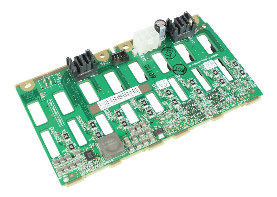
The 8 port backplane can be found for the same price (29€) as most sellers are asking for the 4 port model, and simplifies the cabling. You only need one power cable and one I2C cable with the 8 port backplane, although two of each cable are provided in the TX1320. You will need an additional SATA/SAS controller though, as the D3373 has only one Mini-SAS HD connector for up to 4 devices.

You can use the original Molex 5559 power cable (2×2 positions; 2 populated) from the TX1320 with the 8 port backplane without modification; below is the pinout of the original power cable (2×3 positions; 6 populated) marked on the PCB as X40:

A3C40173252 SAS backplane power receptacle (X40)

Older revisions of the backplane also have a Micro-Fit 3.0 (Molex 430450412) populated on the PCB as X17 which offers 12V and 5V voltage outputs. Note that the below pinout is for the cable, not the X17 receptacle:

A3C40173252 X17 cable pinout

Note that you still need to provide cooling for the additional drive bays, which cannot easily be done as the plastic fan duct has no official part number (as noted by Artur in the comments).

Fujitsu iRMC S4 on the TX140 S2

Fujitsu servers come with a remote management solution called iRMC S4 (newer models have iRMC S5). iRMC S4 and S5 are like other lights-out remote management solutions from HP (iLO) or Dell (iDRAC) which comprises a baseband management controller firmware along with other software utilities to remotely configure and manage servers. Importantly though, iRMC S4 runs Linux.


Before we get into the hardware of iRMC S4, let us examine the firmware update process. iRMC S4 follows a pretty typical BMC firmware update process: Fujitsu’s support website offers firmware downloads, and the iRMC web management interface allows you to upload the update which is then written to the inactive firmware slot.

As is common for enterprise hardware, there is no rollback protection, so you can downgrade the installed firmware to previous versions. I did not extensively test this functionality though, so there may be limits to how far you can downgrade as the firmware modifies the persistent conf partition (which is not redundant).

Running binwalk against the update file for the TX140 S2, we can immediately see that it is not encrypted:

$ binwalk FTS_TX140S2D3239iRMCKronos4FirmwareUpdatefo_TX140S20960Fsdr0344_1233853.BIN 

DECIMAL       HEXADECIMAL     DESCRIPTION
--------------------------------------------------------------------------------
148820        0x24554         U-Boot version string, "U-Boot 1.1.6 (Sep 22 2015 - 17:25:45)"
150076        0x24A3C         CRC32 polynomial table, little endian
184888        0x2D238         CRC32 polynomial table, little endian
589824        0x90000         uImage header, header size: 64 bytes, header CRC: 0x2658385F, created: 2020-04-01 11:24:03, image size: 27389952 bytes, Data Address: 0x0, Entry Point: 0x0, data CRC: 0x6B45479A, OS: Linux, CPU: ARM, image type: RAMDisk Image, compression type: none, image name: ""
589888        0x90040         CramFS filesystem, little endian, size: 27389952, version 2, sorted_dirs, CRC 0x6745F599, edition 0, 15794 blocks, 4707 files
27983936      0x1AB0040       uImage header, header size: 64 bytes, header CRC: 0x27056A57, created: 2019-11-04 16:46:29, image size: 3042664 bytes, Data Address: 0x80808000, Entry Point: 0x80808000, data CRC: 0x222093D7, OS: Linux, CPU: ARM, image type: OS Kernel Image, compression type: none, image name: "Linux-3.14.17-ami"
27984000      0x1AB0080       Linux kernel ARM boot executable zImage (little-endian)
28002116      0x1AB4744       gzip compressed data, maximum compression, from Unix, last modified: 1970-01-01 00:00:00 (null date)
31129600      0x1DB0000       CramFS filesystem, little endian, size: 45056, version 2, sorted_dirs, CRC 0x52551191, edition 0, 31 blocks, 12 files

As far as I have been able to determine, here is the firmware layout of iRMC S4 on the TX140 S2:

00000000:0008ffff uboot1
00090000:01aaf040 root1 # cramfs1
01ab0040:01daffff zImage1
01db0000:01dc0000 platform1 # sdr1
01e24554:01e8ffff uboot2
01e90000:038af040 root2 # cramfs2
038b0040:03baffff zImage2
03bb0000:03bc0000 platform2 # sdr2
03c00000:03ff0000 conf
03ff0000:03ffffff fru

These correspond to the lower and higher firmware slots in iRMC S4, and ensure that the firmware you are updating is not the currently running firmware.


So, could our way into iRMC S4 be as easy as modifying the cramfs from the firmware update?

Unfortunately, no. The update is signed and the signature is checked by /usr/local/bin/flasher against an RSA-1024 public key located on the conf partition prior to overwriting:

-----BEGIN PUBLIC KEY-----
MIGfMA0GCSqGSIb3DQEBAQUAA4GNADCBiQKBgQCdgO/cGwthsFEZLuohVB5DNvU/
LolrQobsNASL4Sc+uzn8PsULIPiG0v3zhR8zCwlChmF/umVvk1gxKy5cAY0Bj3oo
cUhXwHf4t2ty+2ZY+p975Yg6YonQJSTKVPVfBlk/9PqNRj/Ih5P3zqd80YxAoKhX
i77qhLxjehHLsRSP2QIDAQAB
-----END PUBLIC KEY-----

Attempting to modify and repack cramfs results in the following output to the UART:

[1533 : 1533 INFO]VerifyImage
Signature Verification Failure
[1533 : 1533 CRITICAL][utils.c:1241]Signature verification failed 
[1533 : 1533 CRITICAL][utils.c:1522]Encrypted hash of Image and the actual contents of rom.ima does not match

With our software-only modification route looking grim, it is time to move on into the realm of the evil maid.

On the TX140 S2 the BMC UART (38400n8) has been routed to pads, located just below PCIe slot 2, which are easily soldered to:

BMC UART connections on a Fujitsu TX140 S2 motherboard
BMC UART on the TX140 S2 (D3239) motherboard

To stop the default boot sequence, press Escape within 2 seconds:

U-Boot 1.1.6 (Jun 20 2013 - 09:09:05)

DRAM:  247 MB
Fast clk is set
Found SPI Chip Macronix MX66L51235F 
Flash: 64 MB
Net:   pilot_eth0, pilot_eth1
Hit Esc key to stop autoboot:  0 
------ Boot Options-------
        0. Normal Boot
        1. Diagnostics
        2. Remote Recovery
        3. Management Console
        4. Raw Console
Select Boot Option:

The GPL source code for iRMC S4 was requested in December 2020, and at the time of writing Fujitsu had not provided the source code. Without the source code for u-boot, it is difficult to determine if there are any routes that could lead to easy exploitation.


Getting a root console is relatively straightforward with soldering or a chip jig. If you use a jig, you will need very steady hands as flashrom requires 20-30 minutes to write and verify the 27MB cramfs region.

512MBit MXIC flash of the TX140 S2 iRMC S4 BMC

Lucky me, Fujitsu engineers considered physical modification of the iRMC S4 firmware out of scope, and there is no secure boot or signature verification of the cramfs on flash.

Since we can manipulate cramfs, we can bypass the stock Fujitsu shell and replace /usr/local/bin/remman with a symlink to /bin/sh and SSH as the admin user. This is not particularly useful though, as the admin user is not root sysadmin, and the busybox that Fujitsu ship is lacking the su applet, so there’s no way to easily escalate your privileges from admin to sysadmin once logged in.

~ $ id
uid=1002(admin) gid=501(ipmi) groups=501(ipmi),504(lanoem),510(serialoem),528(iRMCsettings),529(RemoteStorage),530(UserAccounts),531(VideoRedirection),532(CfgConnectionBlade),535(RemoteManager)

The uid 0 account is not called root, but rather sysadmin with the password superuser:

sysadmin:$1$A17c6z5w$5OsdHjBn1pjvN6xXKDckq0:18627:0:99999:7:::

The sysadmin account is not visible in the iRMC web interface and, as far as I can tell, the password cannot be changed (unless you physically modify the contents of cramfs). I believe the account is leftover from the SDK that iRMC S4 appears to be based on.

All my attempts to login as sysadmin via SSH or uart with the default remman shell were unsuccessful, so it doesn’t appear to be a security risk out of the box.

However, once you have replaced /usr/local/bin/remman with a symlink to /bin/sh it is possible to login as the sysadmin user and enjoy root access to your iRMC S4.

Fujitsu TX140 S2

The SuperMicro X10SLE-F is nice, but it has very limited expansion; no PCIe slots and the MicroLP adapters with SFP+ are insanely expensive. Fujitsu motherboards, in the EU, are quite cheap (33€ on eBay) and I have never owned a Fujitsu system before, so I thought I would give it a try.

Fujitsu TX140 S2 motherboard

The first order of business, since I bought a bare motherboard, is to power it from an ATX power supply. Luckily for me, other people have determined the 16-pin power supply pinout:

Fujitsu 16-pin power supply pinout

Side note: this appears to be a common power supply connector for Fujitsu motherboards with a 16-pin power connector. The Celsius W520 uses the same pinout.

The 12V rail appears to go directly to the PCIe slots and is completely isolated from 12V V1.


If the ambient temperature sensor is absent, iRMC considers the system in an error state. The Global Error/CSS lights are flashing and the fans run at full speed (100% PWM).

Unfortunately the ambient temperature sensor is integrated into the front-panel assembly (c26361-k644-c550), which I don’t have:

I couldn’t locate the technical manual for the TX140 S2 (D3239), but technical manual of the TX140 S1 (D3049) has the following to say:

Measurement of the processor and the system internal temperature by an onboard temperature sensor, measurement of the ambient temperature by a I²C temperature sensor.

System board D3049 for PRIMERGY TX140 S1 / TX120 S3 – Technical Manual

I am unaware of any publicly available pinout of the 16 pin front-panel header (2×8, 2.0mm spacing), so I reverse engineered it:

Fujitsu TX140 S2 front panel pinout

In table format:

PinDescriptionPinDescription
1SDA (serial data)23.3V
3Ground4SCL (serial clock)
5CSS LED positive (Customer self service)6ID button
7ID LED+ (anode)8NMI button
9Reset button10Global Error LED+ (anode)
11Ground12HDD activity LED+ (anode)
13Standby LED+ (anode)14Power LED+ (anode)
15Power button16Key (pin absent)
Fujitsu TX140 S2 front panel pinout

We can confirm the I²C pins with a logic analyzer:

I²C found

Now unfortunately, there are no high resolution photos of the front-panel PCB, so it’s not possible to easily determine which I²C temperature sensor is being used.

There is a photo of a Fujitsu RX300 front-panel with a failed temperature sensor, but that is only enough to allow us to guess the chip model as the Texas Instruments LM75.

The CJMCU-75 is a cheap and readily available LM75 sensor

We can also guess the I²C address from the RX300 front-panel: all 3 address lines should be tied to VCC.

Now with the sensor connected to the front-panel connector using the pinout above, it is time to find out if Fujitsu used the same ambient temperature sensor on the RX300 and TX140 S2, and if I guessed the I2C address correctly.

Yes, iRMC S4 reads the ambient temperature from the CJMCU LM75!

There is a chassis IDPROM also in the front panel assembly, which from the iRMC log appears to store a backup of the BIOS parameters after successful POST. I consider the IDPROM somewhat optional, as iRMC does not consider it a critical component in terms of server functionality.


First impressions are good, power consumption is very low, though not as low as the X10SLE-F. Idle power consumption in Linux is under 20W with an E3-1220 v3 and 16GB of PC3L-12800E.

lspci output:

00:00.0 Host bridge: Intel Corporation Xeon E3-1200 v3 Processor DRAM Controller (rev 06)
00:01.0 PCI bridge: Intel Corporation Xeon E3-1200 v3/4th Gen Core Processor PCI Express x16 Controller (rev 06)
00:01.1 PCI bridge: Intel Corporation Xeon E3-1200 v3/4th Gen Core Processor PCI Express x8 Controller (rev 06)
00:14.0 USB controller: Intel Corporation 8 Series/C220 Series Chipset Family USB xHCI (rev 05)
00:19.0 Ethernet controller: Intel Corporation Ethernet Connection I217-LM (rev 05)
00:1a.0 USB controller: Intel Corporation 8 Series/C220 Series Chipset Family USB EHCI #2 (rev 05)
00:1c.0 PCI bridge: Intel Corporation 8 Series/C220 Series Chipset Family PCI Express Root Port #1 (rev d5)
00:1c.2 PCI bridge: Intel Corporation 8 Series/C220 Series Chipset Family PCI Express Root Port #3 (rev d5)
00:1d.0 USB controller: Intel Corporation 8 Series/C220 Series Chipset Family USB EHCI #1 (rev 05)
00:1f.0 ISA bridge: Intel Corporation C224 Series Chipset Family Server Standard SKU LPC Controller (rev 05)
00:1f.2 SATA controller: Intel Corporation 8 Series/C220 Series Chipset Family 6-port SATA Controller 1 [AHCI mode] (rev 05)
00:1f.3 SMBus: Intel Corporation 8 Series/C220 Series Chipset Family SMBus Controller (rev 05)
00:1f.6 Signal processing controller: Intel Corporation 8 Series Chipset Family Thermal Management Controller (rev 05)
03:00.0 VGA compatible controller: Matrox Electronics Systems Ltd. MGA G200e [Pilot] ServerEngines (SEP1) (rev 05)
03:00.1 Co-processor: Emulex Corporation ServerView iRMC HTI
04:00.0 Ethernet controller: Intel Corporation I210 Gigabit Network Connection (rev 03)

I have requested the GPL source code of iRMC from Fujitsu, and if they get back to me with the source code I may have some interesting findings to share. Stay tuned…