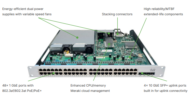
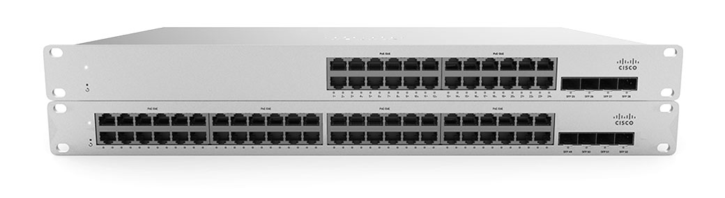
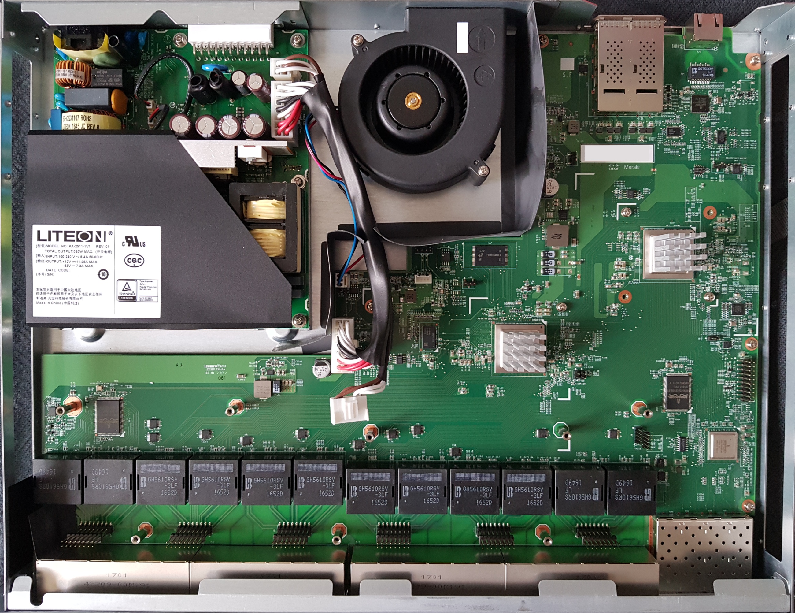
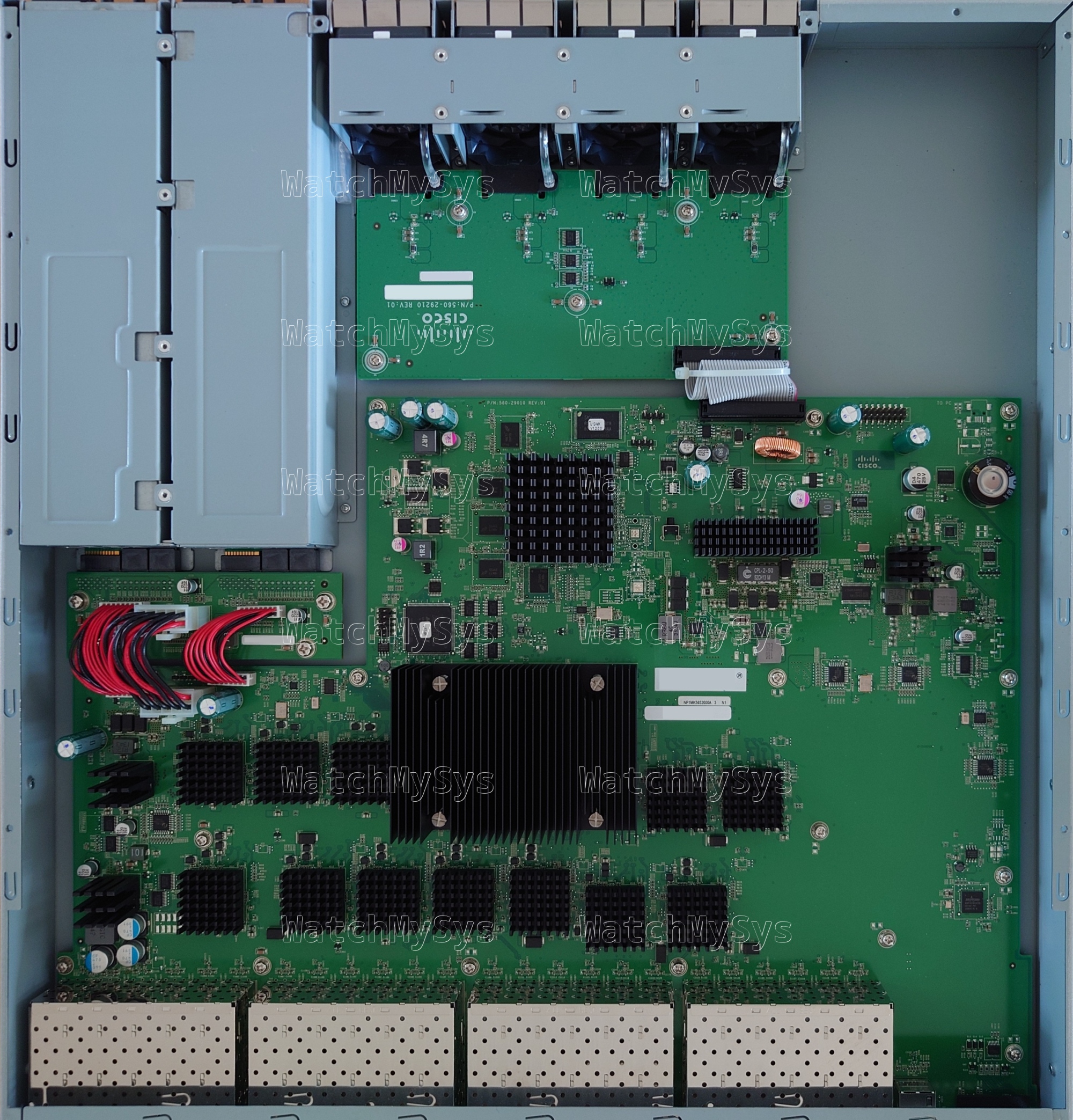
The Meraki MS420 series switches (codename “Fatboy”) offer 24 or 48 ports of 10G SFP+, with a dedicated gigabit Ethernet port for remote management.
The MS420 series does not support dedicated stacking capabilities, although you can always connect multiple switches together via SFP+.
The MS420 was discontinued in 2016, and is too old to support secure boot.
Here is a quick summary of the MS420 specs:
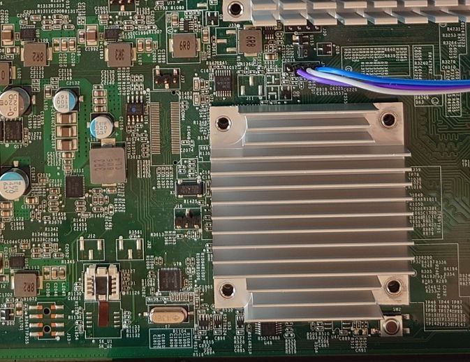
- Broadcom BCM56840 family “Trident+” ASIC (Product Brief PDF). The BCM56846 is used for both 24 and 48 port models.
- BCM84754 SFI-to-XFI PHY
- Freescale P2020E (PowerPC) dual-core management CPU @ 1GHz
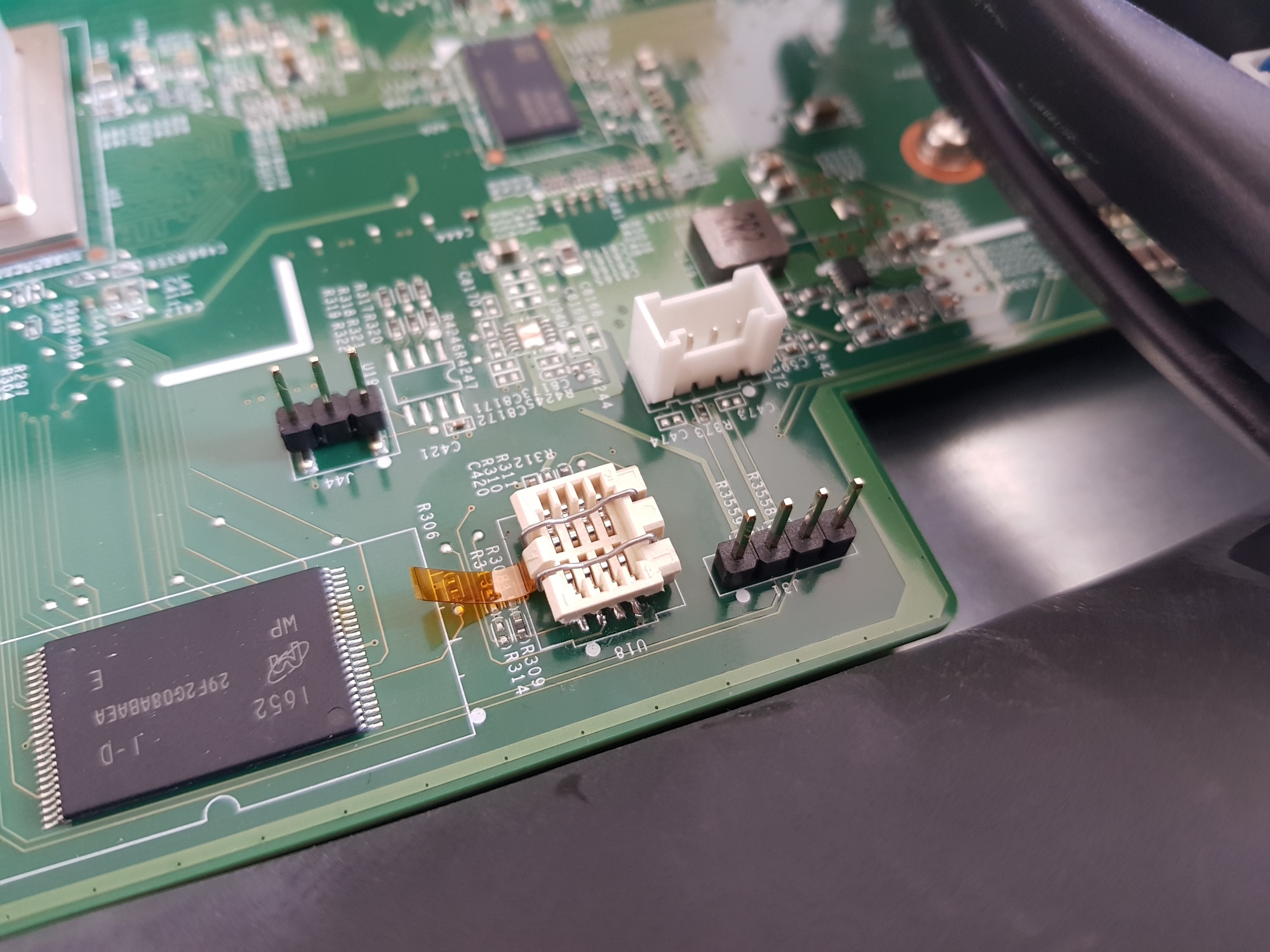
- 128MB NAND (Hynix H27U1G8F2BTR-BC)
- 2048MB DDR3 ECC RAM (soldered)
Like the PowerPC-based Meraki MX60 and MX80, the MS420-series uses Kernel 3.4.113.
Similar to other Meraki Broadcom-based switches, the MS420 series implements the packet engine in userspace, using the linux_kernel_bde and linux_user_bde kernel modules to interface with the ASIC. In the Meraki firmware, the packet engine is a component of the userspace click daemon, which loads the bcm_click shared object during click router initialisation.
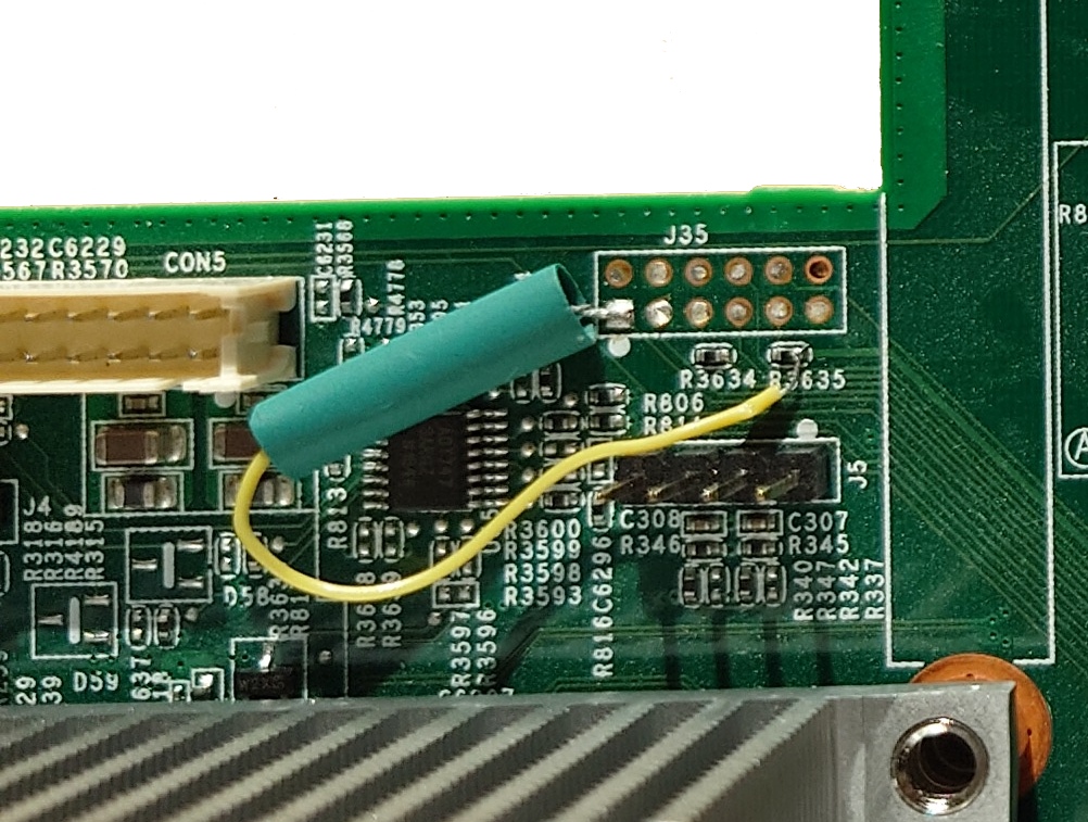
The UART header is CONN4 on the MS420 and follows the standard Meraki UART pinout (1: VCC, 2: Tx, 3: Rx, 4: GND) at 115200 baud.
The u-boot release on the MS420 is 2013.10 and allows interrupting the autoboot with the magic string xyzzy, as found on other older Meraki products before they disabled the boot delay. Therefore, you can interrupt the boot process, although you have only a few seconds to do so:
NAND boot... transfering control to secondary loader
Starting secondary loader ...
Booting U-boot
transfering control


U-Boot 2013.10-g9a6f165 (Mar 11 2016 - 20:09:33)

CPU0:  P2020E, Version: 2.1, (0x80ea0021)
Core:  e500, Version: 5.1, (0x80211051)
Clock Configuration:
       CPU0:1000 MHz, CPU1:1000 MHz,
       CCB:333.333 MHz,
       DDR:333.333 MHz (666.667 MT/s data rate) (Asynchronous), LBC:41.667 MHz
L1:    D-cache 32 KiB enabled
       I-cache 32 KiB enabled
Board: Fatboy
I2C:   ready
DRAM:  2 GiB (DDR3, 64-bit, CL=6, ECC on)
L2:    512 KiB enabled
NAND:  128 MiB
*** Warning - bad CRC, using default environment

PCIe1: Root Complex, x1, regs @ 0xff70a000
  01:00.0     - 14e4:b846 - Network controller
PCIe1: Bus 00 - 01
PCIe2: Root Complex, no link, regs @ 0xff709000
PCIe2: Bus 02 - 02
In:    serial
Out:   serial
Err:   serial
init GPIO
init REAR FAN I2C to output
register sysled device
Set Fan in Full Speed
Net:   eTSEC1 [PRIME]
autoboot in 3 seconds
LOADER=>
Once you have gained access to the u-boot console it is possible to tftpboot your own payload.
The P2020E boots directly off NAND, without an intermediate “bootkernel” on SPI flash (as is the case on the MS220, MS210/225, and MS350).
Booting is not as straightforward as just creating a FIT image. Similar to the MX80, Meraki have created a custom image format which includes a header with additional data used to validate the integrity of the image.
The layout of the image header for the MS420 is as follows:
| Header field | Data type (value) |
|---|---|
SHA1_MAGIC |
uint32 (0x8e73ed8a) |
DATA_OFFSET |
int32 (0x0000400) |
DATA_LEN |
int32 |
SHA1SUM |
char[20] |
0000:00:00.0 PCI bridge: Freescale Semiconductor Inc P2020E (rev 21)
0001:02:00.0 PCI bridge: Freescale Semiconductor Inc P2020E (rev 21)
0001:03:00.0 Ethernet controller: Broadcom Corporation Device b846 (rev 02)
The switch contains a discrete I2C RTC (NXP PCF8563), however there is no battery present so the RTC does not retain the time across power cycles.
rtc-pcf8563 2-0051: low voltage detected, date/time is not reliable.
rtc-pcf8563 2-0051: setting system clock to 2010-03-21 03:00:00 UTC (1269140400)
The four 40mm system fans in the MS420 are controlled by an onsemi ADT7473 (PDF datasheet). It appears that only the internal temperature sensor of the ADT7473 is present (for anyone else wondering, digging into the kernel module reveals that temp1 corresponds to Remote 1 Temperature, temp2 to Local Temperature, and temp3 to Remote 2 Temperature). The Meraki firmware does a respectable job of managing fan speed; after booting and settling, the fans are not quite the 1U screamer as you might expect from such a switch. They are still audible, but it is tolerable and being near the switch does not require an investment in hearing protection.
The MS420 fans have a Meraki part number: FAN-MS420-R (P/N 680-29010). These are identical to the Cisco FAN-T1, which can be purchased for considerably less than the Meraki branded part.
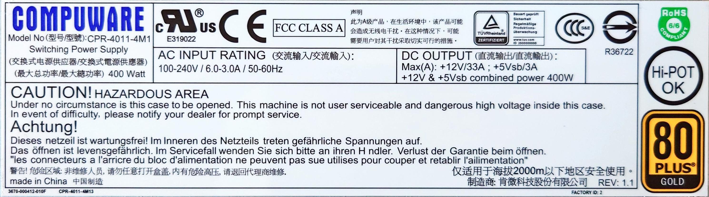
The MS420 accepts two hot-swap power supplies (model PWR-MS420-400AC-R, P/N 640-29010), which in my units are Compuware model CPR-4011-4M1 with 12V/33A and 5Vsb/3A output (combined power 400W) and are 80+ Gold certified:
MS420-24 idle power consumption: ~85W (single PSU)
MS420-48 idle power consumption: ~100W (single PSU)
The GPL source code for the MS420 was requested from Meraki in July 2023 and at the time of writing Meraki has not provided any of the requested source code.
There are other Trident+ switches (like the Arista DCS-7050S) that can be purchased for around $200 USD, and do not require any additional effort to use. Unless you have decommissioned MS420 switches, I would recommend against buying one as there are better options available.
| Model | Meraki Board | Part number |
|---|---|---|
| MS420-24 | FATBOY | 600-29020 |
| MS420-48 | FATBOY | 600-29010 |