In the last article on this topic, I unbricked my Western Digital My Cloud EX2100 NAS and said I would provide instructions on how to install Debian. There are partial instructions for how to replace the stock u-boot with one that is capable of booting Debian from a USB stick, but following those instructions requires slightly more knowledge about how the boot process works and omits some important details.
Now that I have the EX2100 working again, I thought it would be good to provide a set of complete, concise installation instructions for anyone else with this hardware who is interested in running Debian (or another Linux) on it. These instructions are also available on the Doozan forum.
Uart
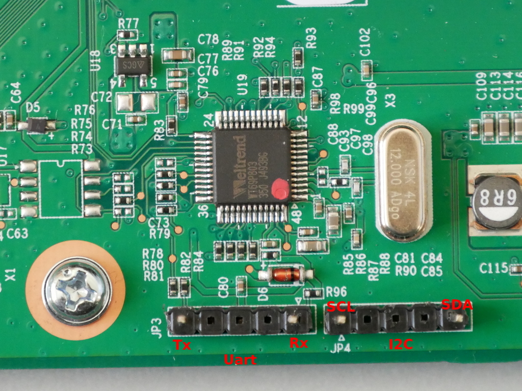
Before we begin installation of Debian, you will need a working uart connection to the EX2100.
There are two possible methods to connect via uart:
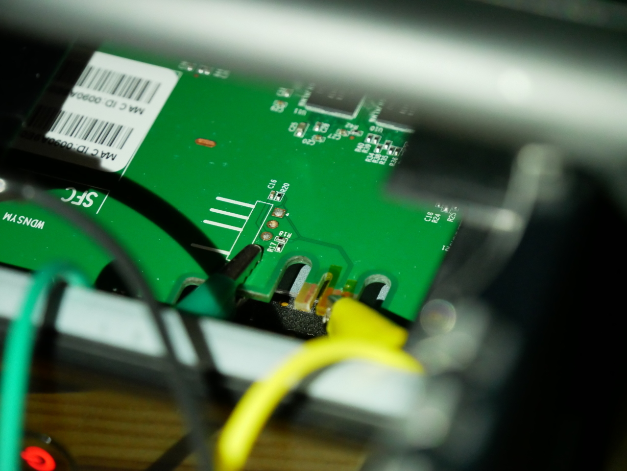
- solder a header to JP1 the PCB to expose Rx, Tx, and Gnd. This will require opening the enclosure and removing the PCB, which will void your warranty
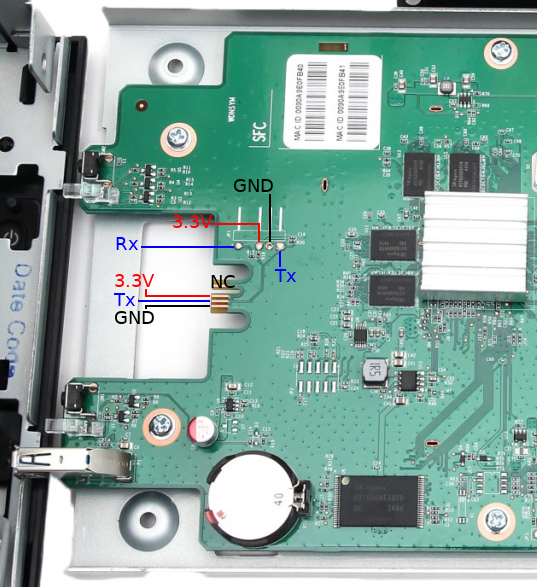
- Using kapton tape (tweezers, and patience), cover the 3.3V and GND pads on the front of the PCB. Use alligator clips to attach to the Tx contact, the Rx pad from JP1, and the chassis for ground. This method is not as reliable as soldering a header to JP1, but does not require disassembly and soldering as the area can be accessed by opening the hard drive bay doors
Test the connection by powering up the EX2100 with a USB to uart adapter or something like a Raspberry Pi. The uart operates at 115200n8.
You should immediately see output from u-boot (see sample below). If you don’t see any output, check your connections and ensure that you have not reversed the uart Tx/Rx.
Uart output
BootROM - 1.73

Booting from NAND flash
General initialization - Version: 1.0.0
Detected Device ID 6820
High speed PHY - Version: 2.0
Load WD Yosemite Serdes Config:
board SerDes lanes topology details:
| Lane # | Speed | Type |
--------------------------------
| 0 | 06 | SATA0 |
| 1 | 05 | PCIe0 |
| 2 | 06 | SATA1 |
| 3 | 05 | USB3 HOST1 |
| 4 | 05 | USB3 HOST0 |
| 5 | 00 | SGMII2 |
--------------------------------
PCIe, Idx 0: detected no link
High speed PHY - Ended Successfully
DDR3 Training Sequence - Ver TIP-1.26.0
mvSysEnvGetTopologyUpdateInfo: TWSI Read failed
DDR3 Training Sequence - Switching XBAR Window to FastPath Window
DDR3 Training Sequence - Ended Successfully
BootROM: Image checksum verification PASSED
__ __ _ _
| \/ | __ _ _ ____ _____| | |
| |\/| |/ _` | '__\ \ / / _ \ | |
| | | | (_| | | \ V / __/ | |
|_| |_|\__,_|_| \_/ \___|_|_|
_ _ ____ _
| | | | | __ ) ___ ___ | |_
| | | |___| _ \ / _ \ / _ \| __|
| |_| |___| |_) | (_) | (_) | |_
\___/ |____/ \___/ \___/ \__|
** LOADER **
Prepare a USB with the Debian rootfs for mvebu
For this step you will need a USB mass storage device of at least 2GB. We will format the device, so ensure you do not have any important data on it. The device must be USB 2.0 as USB 3.0 is not supported in the EX2100 u-boot.
Format the device with a single ext3 partition. Double check the device before proceeding as parted will erase and format the device without confirmation!
sudo parted --script /dev/sdX \ mklabel msdos \ mkpart primary ext3 1MiB 100%

sudo mkfs.ext3 -L rootfs /dev/sdX1
Download the latest Debian rootfs from the Doozan forums.
Now, mount the new partition and extract the Debian rootfs:
ROOTFSDIR=$(mktemp -d)

sudo mount /dev/sdX1 $ROOTFSDIR

sudo tar -C $ROOTFSDIR -jxvf Debian-4.12.4-mvebu-tld-1-rootfs-bodhi.tar.bz2
You can download the EX2100 DTB from the kernel image Doozan user bodhi publishes. Inside the kernel archive is another archive containing the DTBs (linux-dtb-$(kernelversion).tar). Extract the archive containing DTBs, and append the EX2100 DTB to the kernel:
tar -C $ROOTFSDIR/boot/dts/ -xvf linux-dtb-4.14.1-mvebu-tld-1.tar

cd $ROOTFSDIR/boot/

cat zImage dts/armada-385-wd-ex2100.dtb > zImage.fdt

mkimage -A arm -O linux -T kernel -C none -a 0x00008000 -e 0x00008000 -n Linux-4.12.4-mvebu-tld-1 -d zImage.fdt uImage
Download u-boot for the EX2100 from here. Extract the archive:
tar -zxvf u-boot-a38x-Yosemite_2014T3_PQ.tar.gz
Copy the file u-boot-a38x-Yosemite_2014T3_PQ-nand.bin to the rootfs:
cp u-boot-a38x-Yosemite_2014T3_PQ-nand.bin $ROOTFSDIR/root/
Unmount the USB device from your computer:
sudo umount $ROOTFSDIR
Put the USB device in the rear USB port on the EX2100. The front USB port cannot be used for booting as it is not powered during u-boot execution.
kwboot the EX2100
Now that you have a serial connection to the EX2100 and a USB device prepared with the Debian rootfs, mvebu kernel, and dtb for the EX2100 it’s time to start installing Debian.
You must use a modified version of kwboot to load u-boot to the EX2100 via uart. You can obtain the modified kwboot binary for amd64 from here, and kwboot for armhf from here.
You will be kwbooting a modified version of u-boot which can save environment variables.
With the EX2100 powered off and unplugged, execute kwboot (note this is one line):
./kwboot -f -t -B 115200 /dev/ttyUSB0 -b u-boot-a38x-Yosemite_2014T3_PQ-nand-uart.bin -s 0 -q 1
Plug the DC power into the EX2100. If the handshake is successful, kwboot should display a loading screen:
Sending boot message. Please reboot the target...-�$�"Ufw�$�"U����$

Dfw�$�"U�\�$�"U����$�DUf�$�"Uw��"U����$4"U���$�"Uw�$�"U���$�DUf|fD�&T���$�"U�E�$�"Df3DD�DU�E7$�"U����$4"U���$�"U�E�4"U�/7@� ��$DUw�$�"U����$�DUff�$�"D��fD$U��

Sending boot image...

  0 % [......................................................................]
If the handshake was unsuccessful, you will see normal u-boot output as you should have seen in the “Uart output” section above. Repeat the procedure until you see kwboot say “Sending boot image…” followed by loading u-boot via uart. This takes some time (~90 seconds).
After the u-boot image has been loaded via kwboot, it will boot normally (as you saw in “Uart output” section above).
When the uart output gets to the following section:
Enable HD1

Enable HD2
Begin pressing the 1 key to interrupt the automatic boot process. If you were successful you should now have a u-boot prompt:
Enable HD1

Enable HD2

Net:

|  port  | Interface | PHY address  |

|--------|-----------|--------------|

| egiga0 |   RGMII   |     0x00     |

| egiga1 |   RGMII   |   In-Band    |

| egiga2 |   SGMII   |     0x01     |

egiga0 [PRIME], egiga1, egiga2

Hit any key to stop autoboot:  0

Marvell>> 1111
Set u-boot environment parameters
Press ctrl+c to clear the extra 1 characters and enter the following:
setenv bootdev usb

setenv device '0:1'

setenv load_initrd_addr 0x2900000

setenv load_image_addr 0x02000000

setenv load_initrd 'echo loading uInitrd ...; ext2load $bootdev $device $load_initrd_addr /boot/uInitrd'

setenv load_image 'echo loading Image ...; ext2load $bootdev $device $load_image_addr /boot/uImage'

setenv usb_set_bootargs 'setenv bootargs "console=ttyS0,115200 root=/dev/sda1 rootdelay=10 $mtdparts earlyprintk=serial"'

setenv usb_bootcmd 'echo Booting from USB ...; setenv fdt_skip_update yes; usb start; run load_image; run load_initrd ; run usb_set_bootargs; bootm $load_image_addr $load_initrd_addr'

setenv bootcmd_usb 'usb start; run usb_set_bootargs; run usb_bootcmd; reset'

printenv

run bootcmd_usb
If you performed the previous steps correctly, the EX2100 should now boot Debian from the USB device attached to the rear USB port.
Make a backup of NAND flash
For the changes in u-boot to be persistent, we need to write the modified version of u-boot to NAND.
However, before we do this, we will make a backup of the contents of NAND before modifying it. When booted into Debian, run the following commands:
mkdir nand_backup

cd nand_backup

nanddump --noecc --omitoob -f mtd{0,7}.bin /dev/mtd{0,7}
Make sure you make a copy these backups also in another location!!!
Installing the modified u-boot
Once you have taken a backup of the NAND contents, poweroff the EX2100. Remove the USB and copy the mtd backups you made to your computer for safekeeping.
When you have finished this, follow the instructions again in the “kwboot the EX2100” section but stop at the “Set u-boot environment parameters” section.
This time we will modify the u-boot environment:
setenv bootdev usb

setenv device '0:1'

setenv load_initrd_addr 0x2900000

setenv load_image_addr 0x02000000

setenv load_initrd 'echo loading uInitrd ...; ext2load $bootdev $device $load_initrd_addr /boot/uInitrd'

setenv load_image 'echo loading Image ...; ext2load $bootdev $device $load_image_addr /boot/uImage'

setenv usb_set_bootargs 'setenv bootargs "console=ttyS0,115200 root=/dev/sda1 rootdelay=10 $mtdparts earlyprintk=serial"'

setenv usb_bootcmd 'echo Booting from USB ...; setenv fdt_skip_update yes; usb start; run load_image; run load_initrd ; run usb_set_bootargs; bootm $load_image_addr $load_initrd_addr'

setenv bootcmd_usb 'usb start; run usb_set_bootargs; run usb_bootcmd; reset'

saveenv

run bootcmd_usb
You will then proceed to boot Debian again.
Once in Debian, create /etc/fw_env.config:
echo “/dev/mtd0 0x100000 0x80000 0x20000 4” > /etc/fw_env.config
Check that fw_printenv is able to read the u-boot environment you just saved in the kwboot’d u-boot:
root@debian:~# fw_printenv

CASset=max

MALLOC_len=5

MPmode=SMP

autoload=no

baudrate=115200

boot_order=hd_scr usb_scr mmc_scr hd_img usb_img mmc_img pxe net_img net_scr

bootargs=root=/dev/ram console=ttyS0,115200

…
If you see the u-boot environment variables returned, then the modified u-boot successfully wrote the environment variables to 0x100000
Verify that you are able to write to the u-boot section of NAND (this should be enabled in the EX2100 dtb):
root@debian:~# mtd_debug info /dev/mtd0

mtd.type = MTD_NANDFLASH

mtd.flags = MTD_CAP_NANDFLASH

mtd.size = 5242880 (5M)

mtd.erasesize = 131072 (128K)

mtd.writesize = 2048 (2K)

mtd.oobsize = 64

regions = 0
If instead you see “mtd.flags = MTD_CAP_ROM” then you cannot flash u-boot using the dtb you have booted with. You can download the dts for the EX2100 and build the dtb for your kernel.
If you saw MTD_CAP_NANDFLASH, then proceed to backup the u-boot environment variables to a file:
nanddump --noecc --omitoob -s 0x100000 -l 0x80000 -f ubootenv.bin /dev/mtd0
Erase the u-boot portion of NAND, flash the modified u-boot, and restore the environment variables:
flash_erase /dev/mtd0 0 8

nandwrite -p /dev/mtd0 u-boot-a38x-Yosemite_2014T3_PQ-nand.bin

nandwrite -p /dev/mtd0 -s 0x100000 ubootenv.bin
That’s it, you should be finished. Shutdown the EX2100 and exit kwboot. Using a standard serial console like screen or minicom, connect to the uart if you want to monitor the boot process.
Now when you power the EX2100 it should boot Debian from the USB device plugged into the rear USB port, if it is present. If the USB device is not present, u-boot will fall back to booting the WD firmware from internal flash.
Note that the Western Digital firmware is not fully functional unless you allow it to format your hard drive(s). If you format the drives with the Western Digital firmware and run Debian from USB, then the device should function regardless of the running firmware. If you choose to partition the drives yourself and usually boot Debian, then the WD firmware won’t be very functional as the hard drive(s) are not formatted in the expected layout.