The last several posts in this series have focused primarily on getting a custom firmware running on the Meraki MS220-series switches, without much regard for preserving existing features. Since I am now at a point where my custom firmware is functional as a Layer 2-ish switch, my attention has turned to PoE, since many switches in the series have PoE support and that is feature I think switch owners (especially MS220-8P) are interested in.
From my investigation into libpoecore included in the Meraki firmware, PoE on the MS220-8P appears to be managed by Microsemi’s PD690xx series of Power over Ethernet Management chips (datasheet). The PD690xx series communicates over I2C with the management CPU to manage PoE on the switch ports (enable/disable PoE, set 802.3af/at modes, query power consumed by a PoE device).
We can confirm that the PD690xx communicates via I2C by running poe_server from Meraki’s firmware and enabling I2C tracing in the kernel:
# cat /sys/kernel/debug/tracing/trace
# tracer: nop
#
# entries-in-buffer/entries-written: 1358/1358   #P:1
#
#                              _-----=> irqs-off
#                             / _----=> need-resched
#                            | / _---=> hardirq/softirq
#                            || / _--=> preempt-depth
#                            ||| /     delay
#           TASK-PID   CPU#  ||||    TIMESTAMP  FUNCTION
#              | |       |   ||||       |         |
      poe_server-682   [000] ....   560.356000: i2c_write: i2c-1 #0 a=030 f=0000 l=4 [13-32-0f-ff]
      poe_server-682   [000] ....   560.358000: i2c_result: i2c-1 n=1 ret=1
      poe_server-682   [000] ....   560.358000: i2c_write: i2c-1 #0 a=030 f=0000 l=2 [13-32]
      poe_server-682   [000] ....   560.358000: i2c_read: i2c-1 #1 a=030 f=0001 l=2
      poe_server-682   [000] ....   560.359000: i2c_reply: i2c-1 #1 a=030 f=0001 l=2 [0f-ff]
      poe_server-682   [000] ....   560.359000: i2c_result: i2c-1 n=2 ret=2
      poe_server-682   [000] ....   560.359000: i2c_write: i2c-1 #0 a=030 f=0000 l=4 [13-32-0f-ff]
      poe_server-682   [000] ....   560.360000: i2c_result: i2c-1 n=1 ret=1
      poe_server-682   [000] ....   560.360000: i2c_write: i2c-1 #0 a=030 f=0000 l=4 [13-9e-dc-03]
      poe_server-682   [000] ....   560.362000: i2c_result: i2c-1 n=1 ret=1
I2C tracing is extremely helpful, as running strace against poe_server directly will not yield useful output as to what operations it is performing to configure PoE.
While it is good news that we are able to recover the I2C commands via kernel tracing, it’s bad news in the sense that writing a new daemon to duplicate the features of poe_cli is non-trivial.
Thankfully, with the libpoecore from the Meraki firmware dump and free disassembly tools like Ghidra (sorry Hex-Rays, support MIPS in IDA Free ¯\_(ツ)_/¯), understanding some of the logic behind functionality provided by poe_server and poe_cli becomes much easier.
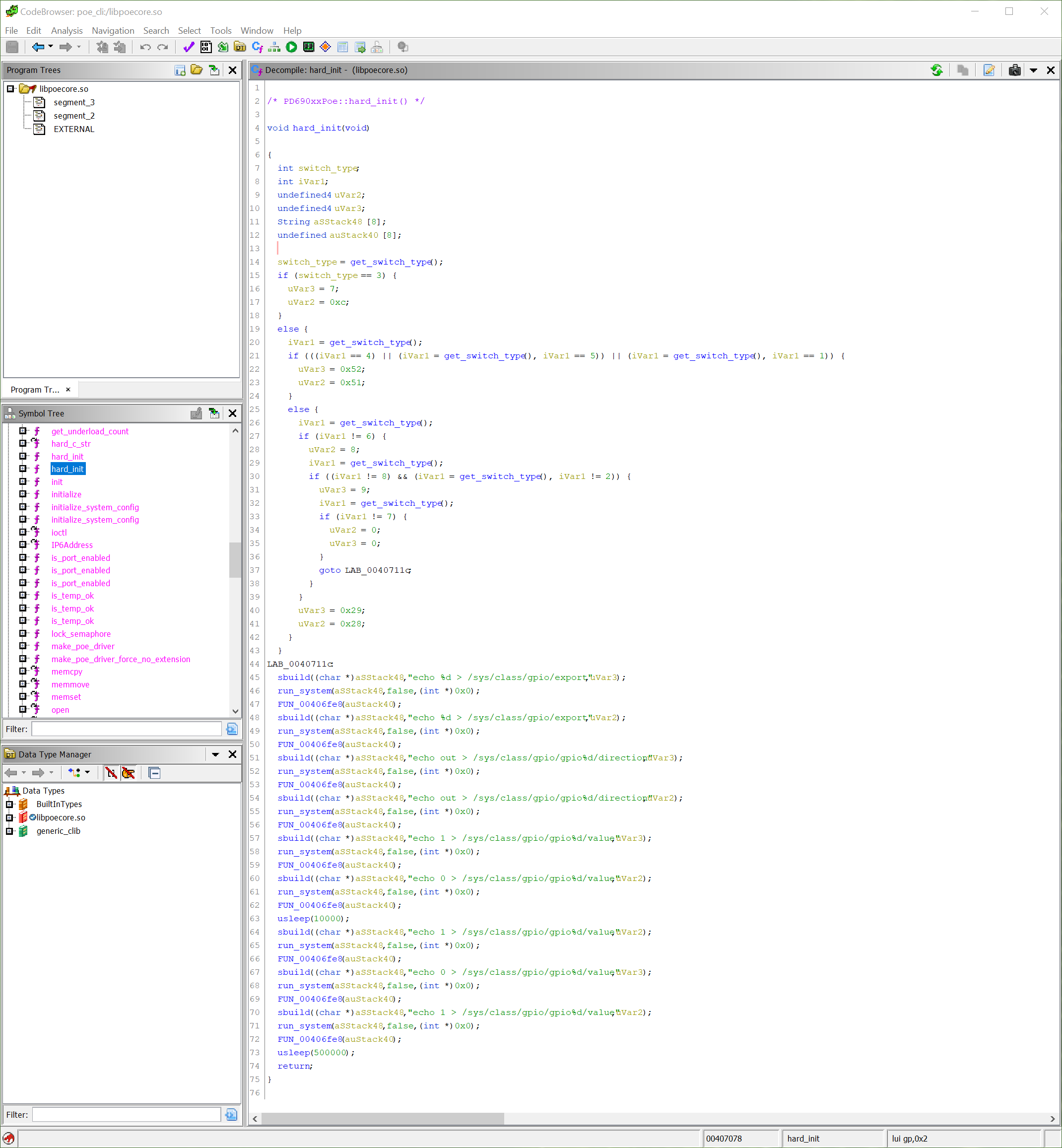
If you disassemble libpoecore, you can find the function hard_init which contains code to set up GPIO outputs. Interesting to note is that while the GPIO pins change depending on which switch ASIC is present, the sequence of GPIO outputs to configure the PD690xx remains constant.
The same GPIO configuration is executed when switch_brain is started (full strace output):
writev(1, [{iov_base="", iov_len=0}, {iov_base="echo 7 > /sys/class/gpio/export\n", iov_len=32}], 2echo 7 > /sys/class/gpio/export) = 32
writev(1, [{iov_base="", iov_len=0}, {iov_base="echo 12 > /sys/class/gpio/export\n", iov_len=33}], 2echo 12 > /sys/class/gpio/export) = 33
writev(1, [{iov_base="", iov_len=0}, {iov_base="echo out > /sys/class/gpio/gpio7/direction\n", iov_len=43}], 2echo out > /sys/class/gpio/gpio7/direction) = 43
writev(1, [{iov_base="", iov_len=0}, {iov_base="echo out > /sys/class/gpio/gpio12/direction\n", iov_len=44}], 2echo out > /sys/class/gpio/gpio12/direction) = 44
writev(1, [{iov_base="", iov_len=0}, {iov_base="echo 1 > /sys/class/gpio/gpio7/value\n", iov_len=37}], 2echo 1 > /sys/class/gpio/gpio7/value) = 37
writev(1, [{iov_base="", iov_len=0}, {iov_base="echo 0 > /sys/class/gpio/gpio12/value\n", iov_len=38}], 2echo 0 > /sys/class/gpio/gpio12/value) = 38
writev(1, [{iov_base="", iov_len=0}, {iov_base="echo 1 > /sys/class/gpio/gpio12/value\n", iov_len=38}], 2echo 1 > /sys/class/gpio/gpio12/value) = 38
writev(1, [{iov_base="", iov_len=0}, {iov_base="echo 0 > /sys/class/gpio/gpio7/value\n", iov_len=37}], 2echo 0 > /sys/class/gpio/gpio7/value) = 37
writev(1, [{iov_base="", iov_len=0}, {iov_base="echo 1 > /sys/class/gpio/gpio12/value\n", iov_len=38}], 2echo 1 > /sys/class/gpio/gpio12/value) = 38
The datasheet for the luton26 ASIC used in the MS220-8P, MS220-24P, and MS22 (VDMS-10393) doesn’t list anything connected to GPIO 7, and GPIO 12 is used for either SFP17_SD or PHY7_LED1 depending on the overlay function chosen. The functionality of these GPIO pins is undefined in the ASIC datasheet, however libpoecore is setting them and manipulating their outputs.
We can implement the logic of hard_init in an init script to set up the GPIO pins in the same way, and the result is that the PD690xx is configured for auto mode. I am not sure how, there is nothing in the PD690xx datasheet which suggests GPIO pins can be used to configure the operating mode, but the switch will automatically negotiate and power a PoE device.
Writing a new daemon to communicate with the PD690xx will ultimately be necessary if fine control over PoE functionality is to be achieved. Without I2C communication to the PD690xx, it is not possible to query the power budget, or limit port power delivery. In the mean time, for those who do not mind unmanaged “plug-and-play” style, PoE can be considered functional.