Tag Archives: vsc7425

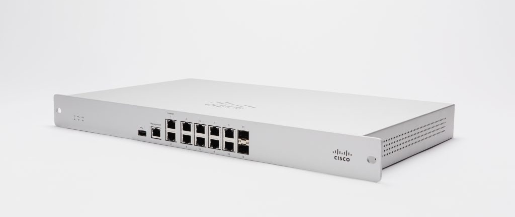
Meraki MX84 overview

I became aware of the Meraki MX84 from Lathe Abusaid’s blog post about tearing down the hardware. After setting up an eBay alert and waiting, I finally won a job lot which included an MX84.


Here is a quick summary of the MX84 specs:

  • Intel Atom C2358 CPU (2C/2T, 1.74GHz)
  • 4GB DDR3 ECC RAM (H5TC4G83CFR-PBA)
  • Internal SATA port (1TB Western Digital Green)
  • External USB2.0 port
  • 13 Network interfaces (Vitesse VSC7425: 11 Gigabit Ethernet, 2 SFP)
  • 16MB SPI flash, 1GB NAND flash (Phison PS2251, USB on motherboard)
  • Fanless
  • Open frame 12V 2.5A power supply

The device runs Linux 3.18.131.

00:00.0 Host bridge: Intel Corporation Atom processor C2000 SoC Transaction Router (rev 02)
00:01.0 PCI bridge: Intel Corporation Atom processor C2000 PCIe Root Port 1 (rev 02)
00:03.0 PCI bridge: Intel Corporation Atom processor C2000 PCIe Root Port 3 (rev 02)
00:0b.0 Co-processor: Intel Corporation Atom processor C2000 QAT (rev 02)
00:0e.0 Host bridge: Intel Corporation Atom processor C2000 RAS (rev 02)
00:0f.0 IOMMU: Intel Corporation Atom processor C2000 RCEC (rev 02)
00:13.0 System peripheral: Intel Corporation Atom processor C2000 SMBus 2.0 (rev 02)
00:14.0 Ethernet controller: Intel Corporation Ethernet Connection I354 1.0 GbE Backplane (rev 03)
00:14.1 Ethernet controller: Intel Corporation Ethernet Connection I354 1.0 GbE Backplane (rev 03)
00:14.2 Ethernet controller: Intel Corporation Ethernet Connection I354 1.0 GbE Backplane (rev 03)
00:14.3 Ethernet controller: Intel Corporation Ethernet Connection I354 1.0 GbE Backplane (rev 03)
00:16.0 USB controller: Intel Corporation Atom processor C2000 USB Enhanced Host Controller (rev 02)
00:17.0 SATA controller: Intel Corporation Atom processor C2000 AHCI SATA2 Controller (rev 02)
00:18.0 SATA controller: Intel Corporation Atom processor C2000 AHCI SATA3 Controller (rev 02)
00:1f.0 ISA bridge: Intel Corporation Atom processor C2000 PCU (rev 02)
00:1f.3 SMBus: Intel Corporation Atom processor C2000 PCU SMBus (rev 02)

The MX84 uses coreboot as the bootloader (coreboot-af6fa06-dirty-Liteon_GRM1001_MFG_v4.0.0; bootlog) and the ROM has the following layout:

00000000:00010000 reserved
00010000:0070ffff bk1
00710000:00dfffff bk2
00e00000:00ffffff coreboot

The cbfs contains the following:

FMAP REGION: COREBOOT
mx84.bin: 16384 kB, bootblocksize 1024, romsize 16777216, offset 0xe00000
alignment: 64 bytes, architecture: x86

Name                           Offset     Type           Size   Comp
cmos_layout.bin                0xe00000   cmos_layout      1352 none
fallback/romstage              0xe00580   (unknown)       25820 none
fallback/ramstage              0xe06ac0   (unknown)       61965 none
fallback/payload               0xe15d40   simple elf      20349 none
config                         0xe1ad00   raw              4310 none
revision                       0xe1be00   raw               712 none
(empty)                        0xe1c100   null          1261208 none
mrc.cache                      0xf4ffc0   mrc_cache       65536 none
cpu_microcode_blob.bin         0xf60000   microcode       84992 none
(empty)                        0xf74c40   null            45912 none
fsp.bin                        0xf7ffc0   spd            389120 none
(empty)                        0xfdf000   null           134040 none

coreboot was built with an ELF payload (miles) which by default loads and jumps into the bootkernel FIT image (dts here) located at 0x10000. A secondary bootkernel exists on flash at offset 0x710000.


Let us revisit those Intel I354 interfaces. As a networking appliance, the MX84 has a lot of network interfaces.

There are 13 network interfaces on the front (Management, Internet 1 & 2, Ethernet 3-10, and 2 SFP cages) so there should be a switch inside the MX84 or we would expect to see more than four interfaces in lspci.

In this case, the switch is the VSC7425, and even if you use the 3.18.131 kernel from Meraki, you won’t have any connectivity because all four of the I354 interfaces connect directly to the VSC7425

The stock Meraki firmware uses a binary called vtss_poca_d to initialise and configure the VSC7425, which does so using a proprietary Vitesse framework (PDF).

vtss_poca_d is a static binary, so could we use it with a newer kernel such as 5.10.146 found in OpenWrt 22.03?

$ vtss_poca_d
mdio_write16: SIOCSMIIREG on eth0 phy:0 reg:0 failed: Not supported
mdio_write16: SIOCSMIIREG on eth0 phy:0 reg:1 failed: Not supported
mdio_write16: SIOCSMIIREG on eth0 phy:0 reg:2 failed: Not supported
mdio_write16: SIOCSMIIREG on eth0 phy:0 reg:3 failed: Not supported
mdio_write16: SIOCSMIIREG on eth0 phy:0 reg:0 failed: Not supported
mdio_write16: SIOCSMIIREG on eth0 phy:0 reg:1 failed: Not supported
mdio_write16: SIOCSMIIREG on eth0 phy:0 reg:2 failed: Not supported
mdio_write16: SIOCSMIIREG on eth0 phy:0 reg:3 failed: Not supported
mdio_write16: SIOCSMIIREG on eth0 phy:0 reg:0 failed: Not supported
mdio_write16: SIOCSMIIREG on eth0 phy:0 reg:1 failed: Not supported
mdio_read16: SIOCGMIIREG on eth0 phy:0 reg:2 failed: Not supported
mdio_read16: SIOCGMIIREG on eth0 phy:0 reg:3 failed: Not supported
mdio_read16: SIOCGMIIREG on eth0 phy:0 reg:2 failed: Not supported
mdio_read16: SIOCGMIIREG on eth0 phy:0 reg:3 failed: Not supported

Nope! As such, it is very unlikely this device will ever be supported by OpenWrt.


You may have noticed that the MX84 is based on the Atom C2000, a CPU which suffers from the AVR54 errata. When I first received my MX84, there was no output on UART and the power consumption was a suspiciously consistent 6W, all the hallmarks of a device dead from AVR54. There are numerous instructions for how to revive a Synology NAS with a dead Atom, but no such instructions exist for the MX84.

Fortunately for me, there was a photo from Lathe Abusaid’s blog post which provided a crucial hint. It appears that the MX84 unit photographed in their teardown includes a 100 Ohm resistor between pins 1 (LPC clock) and 9 (3.3V) of header J7.

This solution appears to have been chosen because it was the most convenient for Cisco, however note that pin 9 of J7 appears to be a GPIO output which, depending on the coreboot payload, may not always be active high. I would suggest instead soldering to pin 8 of the unpopulated SOIC8 nearby (U47), which will provide 3.3V regardless of the payload GPIO configuration.
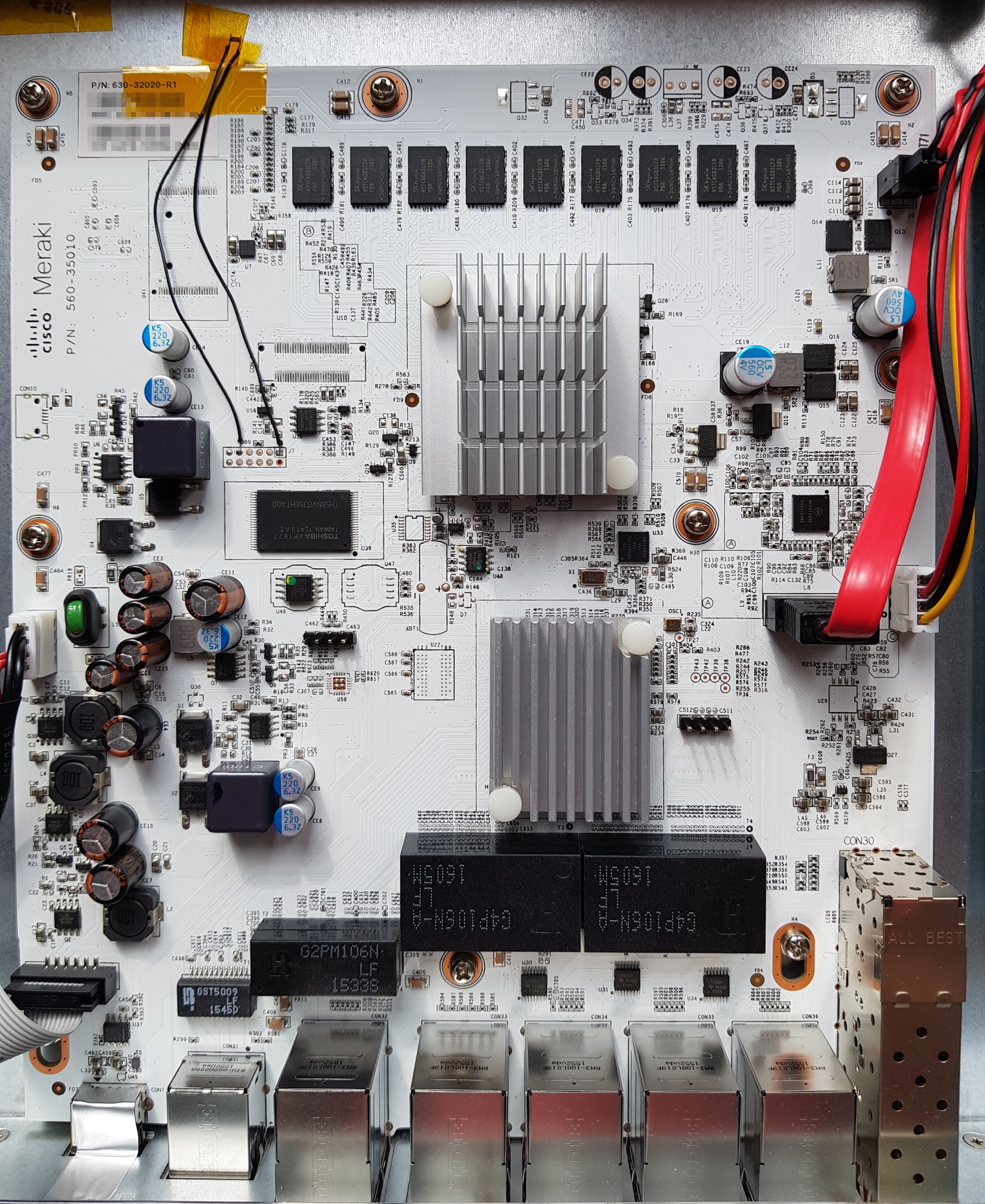
That being said, here is a photo of the resistor fix to J7 that I just advised against doing, taken before realizing pin 9 was a GPIO

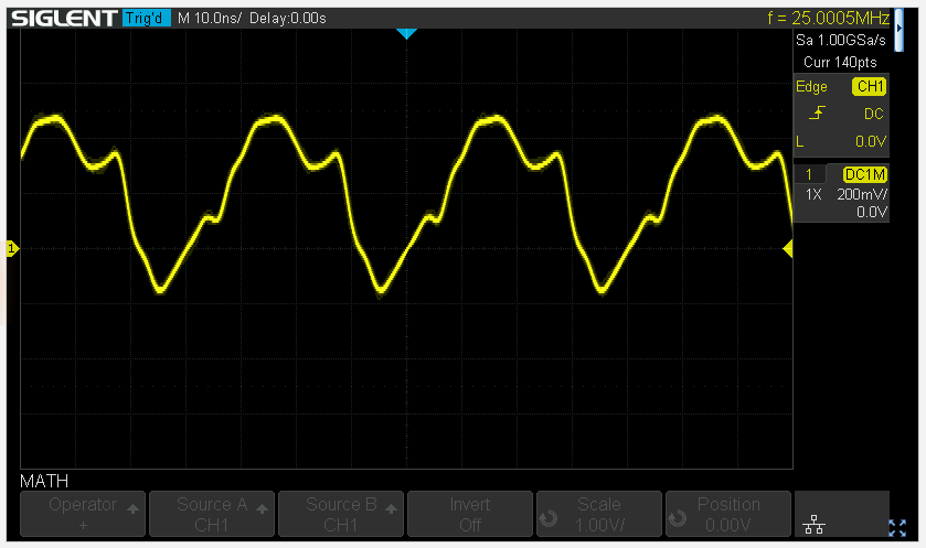
After soldering the pull-up resistor, the LPC clock is back on pin 1 of J7:

Oscilloscope output of the LPC clock on pin 1 of J7 after adding a 100Ω resistor


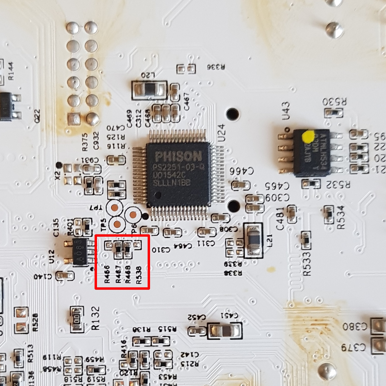
There is an unpopulated footprint for a Micro-USB port on the left side of the motherboard. By default the D-/D+ are not connected, as the 0 Ohm resistors are unpopulated (they are instead populated on R467/R468 connecting the Phison ps2303q to the Atom CPU). I believe this port was used during development to easily swap the USB drive connected to the SoC.


One question I had about the MX84 was: why coreboot? It seems that this design is based on Intel’s “Mohon Peak” reference platform. From the Intel customer reference board (CRB) documentation (PDF):

The embedded firmware ecosystem has developed an example boot loader solution
for the CRB that uses the FSP kit. This solution is based on the open source Coreboot
project at coreboot.org. While Intel does not endorse or support boot loader solutions
based on the Coreboot project, the example Coreboot-based boot loader provides a
good teaching model for how to integrate the Intel FSP into a complete boot loader
solution.

Now it is clear why Meraki chose to use coreboot, that is simply the bootloader reference provided by Intel for Mohon Peak. Other manufacturers who made Atom C2000 products also used coreboot (such as the VeloCloud 520-AC).

Meraki provided the coreboot source code in December 2022, after a delay of more than 12 months. The coreboot source code for the MX84 is available on GitHub.


Meraki hardware commanding the premium that it does, if you are considering buying an MX84: don’t. The VeloCloud 520-AC (C2358) and 540-AC (C2558) are available for ~$30 on eBay and have the C0 revision which doesn’t suffer from AVR54.

If you already own an MX84 and want to poke around, here is a buildroot based firmware that you flash to SPI. The firmware will boot, initialize the switch, DHCP, and start an SSH server (the root password is the device serial without hyphens). Note that it is initramfs based, so no changes are persisted.

Caveat emptor: VeloCloud devices have an issue with the igb/I354 compatibility, meaning that only the two SFP cages are functional. However, that is two more interfaces than you will get from the MX84 (zero) with any other kernel.
Meraki MS220: PoE support

The last several posts in this series have focused primarily on getting a custom firmware running on the Meraki MS220-series switches, without much regard for preserving existing features. Since I am now at a point where my custom firmware is functional as a Layer 2-ish switch, my attention has turned to PoE, since many switches in the series have PoE support and that is feature I think switch owners (especially MS220-8P) are interested in.

From my investigation into libpoecore included in the Meraki firmware, PoE on the MS220-8P appears to be managed by Microsemi’s PD690xx series of Power over Ethernet Management chips (datasheet). The PD690xx series communicates over I2C with the management CPU to manage PoE on the switch ports (enable/disable PoE, set 802.3af/at modes, query power consumed by a PoE device).

We can confirm that the PD690xx communicates via I2C by running poe_server from Meraki’s firmware and enabling I2C tracing in the kernel:

# cat /sys/kernel/debug/tracing/trace
# tracer: nop
#
# entries-in-buffer/entries-written: 1358/1358   #P:1
#
#                              _-----=> irqs-off
#                             / _----=> need-resched
#                            | / _---=> hardirq/softirq
#                            || / _--=> preempt-depth
#                            ||| /     delay
#           TASK-PID   CPU#  ||||    TIMESTAMP  FUNCTION
#              | |       |   ||||       |         |
      poe_server-682   [000] ....   560.356000: i2c_write: i2c-1 #0 a=030 f=0000 l=4 [13-32-0f-ff]
      poe_server-682   [000] ....   560.358000: i2c_result: i2c-1 n=1 ret=1
      poe_server-682   [000] ....   560.358000: i2c_write: i2c-1 #0 a=030 f=0000 l=2 [13-32]
      poe_server-682   [000] ....   560.358000: i2c_read: i2c-1 #1 a=030 f=0001 l=2
      poe_server-682   [000] ....   560.359000: i2c_reply: i2c-1 #1 a=030 f=0001 l=2 [0f-ff]
      poe_server-682   [000] ....   560.359000: i2c_result: i2c-1 n=2 ret=2
      poe_server-682   [000] ....   560.359000: i2c_write: i2c-1 #0 a=030 f=0000 l=4 [13-32-0f-ff]
      poe_server-682   [000] ....   560.360000: i2c_result: i2c-1 n=1 ret=1
      poe_server-682   [000] ....   560.360000: i2c_write: i2c-1 #0 a=030 f=0000 l=4 [13-9e-dc-03]
      poe_server-682   [000] ....   560.362000: i2c_result: i2c-1 n=1 ret=1

I2C tracing is extremely helpful, as running strace against poe_server directly will not yield useful output as to what operations it is performing to configure PoE.

While it is good news that we are able to recover the I2C commands via kernel tracing, it’s bad news in the sense that writing a new daemon to duplicate the features of poe_cli is non-trivial.


Thankfully, with the libpoecore from the Meraki firmware dump and free disassembly tools like Ghidra (sorry Hex-Rays, support MIPS in IDA Free ¯\_(ツ)_/¯), understanding some of the logic behind functionality provided by poe_server and poe_cli becomes much easier.

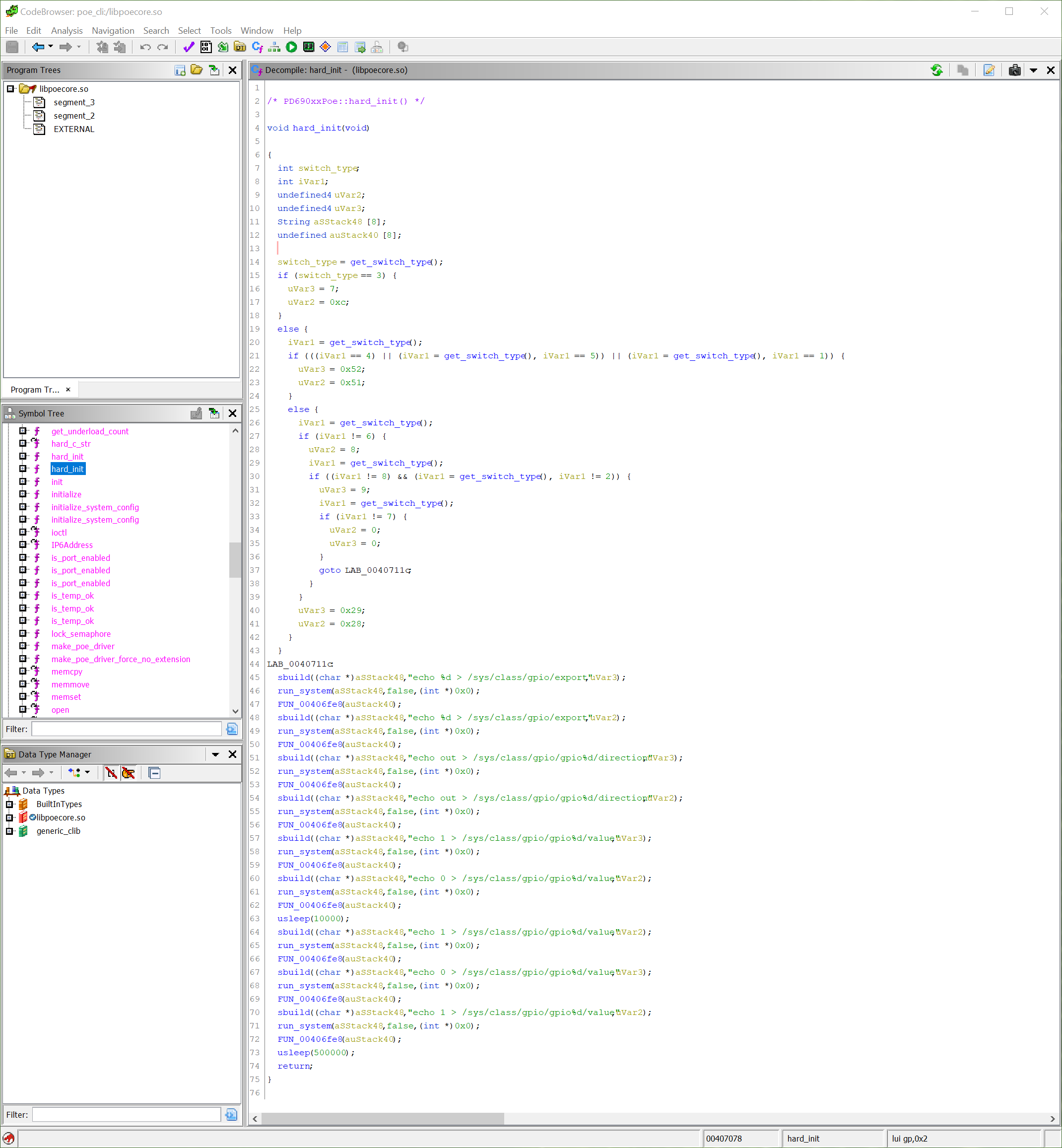
If you disassemble libpoecore, you can find the function hard_init which contains code to set up GPIO outputs. Interesting to note is that while the GPIO pins change depending on which switch ASIC is present, the sequence of GPIO outputs to configure the PD690xx remains constant.

Disassembler view of the function hard_init from the library libpoecore.so

The same GPIO configuration is executed when switch_brain is started (full strace output):

writev(1, [{iov_base="", iov_len=0}, {iov_base="echo 7 > /sys/class/gpio/export\n", iov_len=32}], 2echo 7 > /sys/class/gpio/export) = 32
writev(1, [{iov_base="", iov_len=0}, {iov_base="echo 12 > /sys/class/gpio/export\n", iov_len=33}], 2echo 12 > /sys/class/gpio/export) = 33
writev(1, [{iov_base="", iov_len=0}, {iov_base="echo out > /sys/class/gpio/gpio7/direction\n", iov_len=43}], 2echo out > /sys/class/gpio/gpio7/direction) = 43
writev(1, [{iov_base="", iov_len=0}, {iov_base="echo out > /sys/class/gpio/gpio12/direction\n", iov_len=44}], 2echo out > /sys/class/gpio/gpio12/direction) = 44
writev(1, [{iov_base="", iov_len=0}, {iov_base="echo 1 > /sys/class/gpio/gpio7/value\n", iov_len=37}], 2echo 1 > /sys/class/gpio/gpio7/value) = 37
writev(1, [{iov_base="", iov_len=0}, {iov_base="echo 0 > /sys/class/gpio/gpio12/value\n", iov_len=38}], 2echo 0 > /sys/class/gpio/gpio12/value) = 38
writev(1, [{iov_base="", iov_len=0}, {iov_base="echo 1 > /sys/class/gpio/gpio12/value\n", iov_len=38}], 2echo 1 > /sys/class/gpio/gpio12/value) = 38
writev(1, [{iov_base="", iov_len=0}, {iov_base="echo 0 > /sys/class/gpio/gpio7/value\n", iov_len=37}], 2echo 0 > /sys/class/gpio/gpio7/value) = 37
writev(1, [{iov_base="", iov_len=0}, {iov_base="echo 1 > /sys/class/gpio/gpio12/value\n", iov_len=38}], 2echo 1 > /sys/class/gpio/gpio12/value) = 38

The datasheet for the luton26 ASIC used in the MS220-8P, MS220-24P, and MS22 (VDMS-10393) doesn’t list anything connected to GPIO 7, and GPIO 12 is used for either SFP17_SD or PHY7_LED1 depending on the overlay function chosen. The functionality of these GPIO pins is undefined in the ASIC datasheet, however libpoecore is setting them and manipulating their outputs.

We can implement the logic of hard_init in an init script to set up the GPIO pins in the same way, and the result is that the PD690xx is configured for auto mode. I am not sure how, there is nothing in the PD690xx datasheet which suggests GPIO pins can be used to configure the operating mode, but the switch will automatically negotiate and power a PoE device.

Writing a new daemon to communicate with the PD690xx will ultimately be necessary if fine control over PoE functionality is to be achieved. Without I2C communication to the PD690xx, it is not possible to query the power budget, or limit port power delivery. In the mean time, for those who do not mind unmanaged “plug-and-play” style, PoE can be considered functional.

MS220-8P: Custom firmware from scratch

To follow up on my previous posts about modifying the firmware for the Cisco Meraki MS220-8P, I have more progress to report.

Since I could not figure out how to fix serial output from userspace when booting from u-boot, I went back to booting with RedBoot and tried to focus on improving userspace from my first sloppy attempt to coerce the Meraki firmware into booting from NOR.

Here is the current situation:

  • RedBoot without CRC or kernel size checks
  • Kernel 3.18.123 with xz compression
  • Busybox userspace based on buildroot 2020.02.1
  • Meraki kernel modules: vtss_core, proclikefs, merakiclick, elts_meraki, and vc_click are successfully loaded during boot
  • The click router is successfully initialized, creating the interfaces arping, linux_mgmt, sw0_pcap, and wired0

However, networking is non-functional. The switch broadcasts DHCP requests, but no packets are ever passed from the switching ASIC to the management CPU:

arping    Link encap:Ethernet  HWaddr 88:15:44:73:22:31
          inet addr:169.254.55.143  Bcast:169.254.255.255  Mask:255.255.0.0
          inet6 addr: fe80::8a15:44ff:fe73:2231/64 Scope:Link
          UP BROADCAST RUNNING MULTICAST  MTU:1500  Metric:1
          RX packets:0 errors:0 dropped:0 overruns:0 frame:0
          TX packets:33 errors:0 dropped:0 overruns:0 carrier:0
          collisions:0 txqueuelen:0
          RX bytes:0 (0.0 B)  TX bytes:5546 (5.4 KiB)

linux_mgmt Link encap:UNSPEC  HWaddr 00-00-00-00-00-00-00-00-00-00-00-00-00-00-00-00
          UP POINTOPOINT RUNNING NOARP MULTICAST  MTU:1500  Metric:1
          RX packets:0 errors:0 dropped:0 overruns:0 frame:0
          TX packets:0 errors:0 dropped:0 overruns:0 carrier:0
          collisions:0 txqueuelen:0
          RX bytes:0 (0.0 B)  TX bytes:0 (0.0 B)

lo        Link encap:Local Loopback
          inet addr:127.0.0.1  Mask:255.255.255.255
          inet6 addr: ::1/128 Scope:Host
          UP LOOPBACK RUNNING  MTU:65536  Metric:1
          RX packets:0 errors:0 dropped:0 overruns:0 frame:0
          TX packets:0 errors:0 dropped:0 overruns:0 carrier:0
          collisions:0 txqueuelen:0
          RX bytes:0 (0.0 B)  TX bytes:0 (0.0 B)

sw0_pcap  Link encap:Ethernet  HWaddr 00:01:02:03:04:05
          inet addr:169.254.83.119  Bcast:169.254.255.255  Mask:255.255.0.0
          inet6 addr: fe80::201:2ff:fe03:405/64 Scope:Link
          UP BROADCAST RUNNING MULTICAST  MTU:1500  Metric:1
          RX packets:0 errors:0 dropped:0 overruns:0 frame:0
          TX packets:32 errors:0 dropped:0 overruns:0 carrier:0
          collisions:0 txqueuelen:0
          RX bytes:0 (0.0 B)  TX bytes:5476 (5.3 KiB)

wired0    Link encap:UNSPEC  HWaddr 00-00-00-00-00-00-00-00-00-00-00-00-00-00-00-00
          UP POINTOPOINT RUNNING NOARP MULTICAST  MTU:1500  Metric:1
          RX packets:0 errors:0 dropped:0 overruns:0 frame:0
          TX packets:0 errors:0 dropped:0 overruns:0 carrier:0
          collisions:0 txqueuelen:0
          RX bytes:0 (0.0 B)  TX bytes:0 (0.0 B)

On the other side:

tcpdump: listening on eth1, link-type EN10MB (Ethernet), capture size 262144 bytes
06:02:32.423798 IP6 (hlim 1, next-header Options (0) payload length: 36) fe80::201:c0ff:fe1f:9fb2 > ff02::16: HBH (rtalert: 0x0000) (padn) [icmp6 sum ok] ICMP6, multicast listener report v2, 1 group record(s) [gaddr ff02::1:ff1f:9fb2 to_ex { }]
06:02:33.097129 IP6 (hlim 1, next-header Options (0) payload length: 36) fe80::201:c0ff:fe1f:9fb2 > ff02::16: HBH (rtalert: 0x0000) (padn) [icmp6 sum ok] ICMP6, multicast listener report v2, 1 group record(s) [gaddr ff02::1:ff1f:9fb2 to_ex { }]
06:03:20.969517 IP (tos 0x0, ttl 64, id 20247, offset 0, flags [none], proto UDP (17), length 332, bad cksum 2a8b (->1677)!)
    0.0.10.10.68 > 10.10.255.255.67: [bad udp cksum 0x17ca -> 0x03b6!] BOOTP/DHCP, Request from 88:15:44:21:65:10 (oui Unknown), length 304, xid 0xd3650d76, secs 123, Flags [none] (0x0000)
          Client-Ethernet-Address 88:15:44:21:65:10 (oui Unknown)
          Vendor-rfc1048 Extensions
            Magic Cookie 0x63825363
            DHCP-Message Option 53, length 1: Discover
            Client-ID Option 61, length 15: hardware-type 255, 44:21:65:10:00:03:00:01:88:15:44:21:65:10
            SLP-NA Option 80, length 0""
            NOAUTO Option 116, length 1: Y
            MSZ Option 57, length 2: 1472
            Hostname Option 12, length 13: "m881544216510"
            T145 Option 145, length 1: 1
            Parameter-Request Option 55, length 14:
              Subnet-Mask, Classless-Static-Route, Static-Route, Default-Gateway
              Domain-Name-Server, Hostname, Domain-Name, MTU
              BR, Lease-Time, Server-ID, RN
              RB, Option 119
            END Option 255, length 0
06:04:25.620540 IP (tos 0x0, ttl 64, id 13784, offset 0, flags [none], proto UDP (17), length 332, bad cksum 43ca (->2fb6)!)
    0.0.10.10.68 > 10.10.255.255.67: [bad udp cksum 0x178a -> 0x0376!] BOOTP/DHCP, Request from 88:15:44:21:65:10 (oui Unknown), length 304, xid 0xd3650d76, secs 187, Flags [none] (0x0000)
          Client-Ethernet-Address 88:15:44:21:65:10 (oui Unknown)
          Vendor-rfc1048 Extensions
            Magic Cookie 0x63825363
            DHCP-Message Option 53, length 1: Discover
            Client-ID Option 61, length 15: hardware-type 255, 44:21:65:10:00:03:00:01:88:15:44:21:65:10
            SLP-NA Option 80, length 0""
            NOAUTO Option 116, length 1: Y
            MSZ Option 57, length 2: 1472
            Hostname Option 12, length 13: "m881544216510"
            T145 Option 145, length 1: 1
            Parameter-Request Option 55, length 14:
              Subnet-Mask, Classless-Static-Route, Static-Route, Default-Gateway
              Domain-Name-Server, Hostname, Domain-Name, MTU
              BR, Lease-Time, Server-ID, RN
              RB, Option 119
            END Option 255, length 0

The primary reason for this appears to be because Meraki is using the click modular router. Click seems to be an attempt to lobotomize the Linux kernel networking stack for the sake of writing academic research papers. The kernel side of click was never upstreamed to mainline and is no longer maintained. Let us pour one out for the poor soul at Cisco who has to maintain this.

Since Meraki was spun out of MIT and the researchers who wrote Click were also at MIT, the relationship between Meraki and Click is clear. Finally Click found a practical use, in a now-obsolete product line from Cisco.

More reverse engineering is necessary to make Click functional enough to have basic connectivity to the management CPU.


The strace output of switch_brain is available in this gist. By first running switch_brain, and then overwriting the default traffic rules with “allow all” I was able to SSH to the management CPU:

/ # echo "allow all" > /click/nat/common_switch_nat/from_smc_filter/config
/ # echo "allow all" > /click/nat/common_switch_nat/from_mgmt_filter/config
/ # tail /tmp/messages | grep dropbear
Jan  1 00:15:49 buildroot authpriv.info dropbear[680]: Child connection from 10.10.10.1:39248
Jan  1 00:15:50 buildroot authpriv.notice dropbear[680]: Password auth succeeded for 'root' from 10.10.10.1:39248
/ # w
USER            TTY             IDLE    TIME             HOST
root            pts/0           00:00   Jan  1 00:15:50  10.10.10.1

I think it is now very clear that the “only” thing blocking full access to the management CPU is the Click configuration. My hope is to build the configuration from the switch_brain strace output and package that into an initscript.

I have updated the meraki-builder repository with the buildroot config file and overlay directory I use to inject init scripts (among other things).

If you would like to contribute, I have written some installation instructions for the current development firmware. If you find the correct voodoo of Click commands to access the management CPU, please open a PR 🥰 The voodoo has been found.