The Meraki MG21, introduced in 2019, is a Cat 6 LTE gateway intended for fail-over connectivity. It features a soldered modem module and either two internal (MG21) or two external (MG21E) antennas.
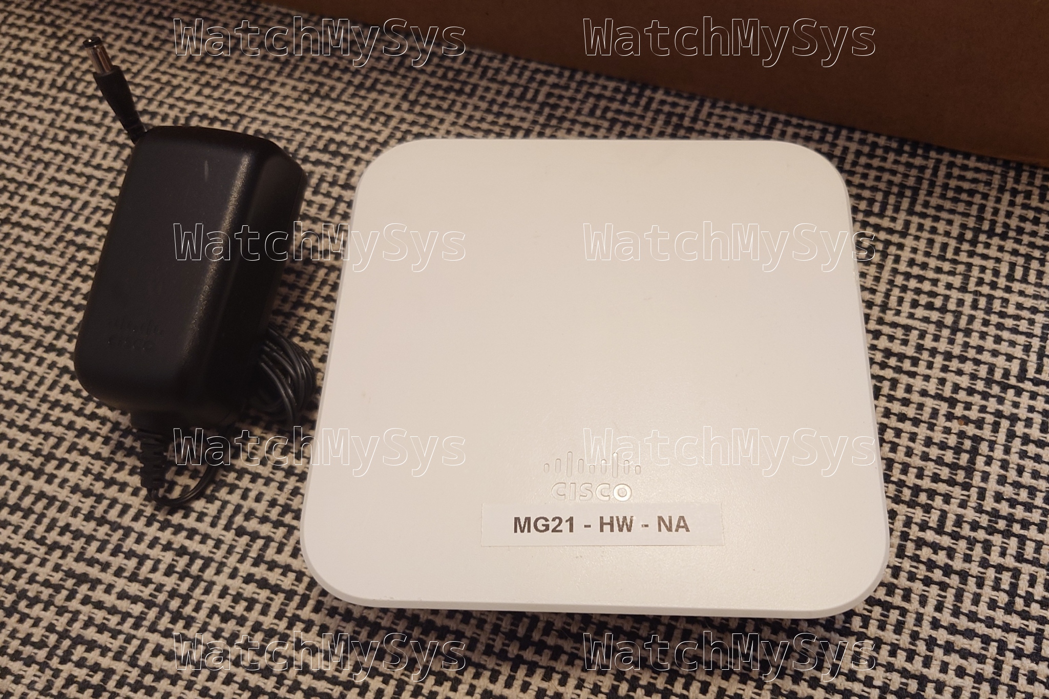
Meraki MG21 LTE gateway
Here is a summary of the MG21 specs:
- Qualcomm IPQ4029 (ARM A7, 4 cores @ ~700MHz)
- 512MB DDR3 RAM (soldered)
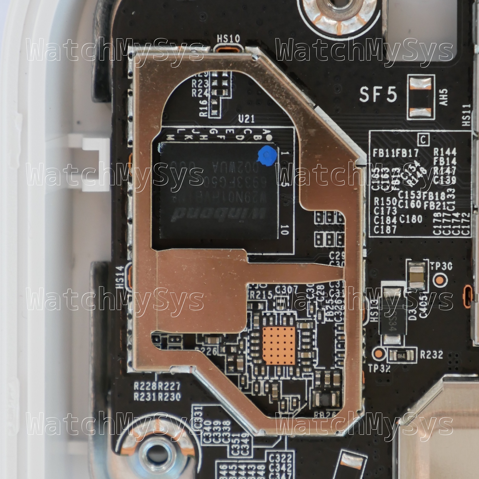
- 128MB of NAND flash (Winbond W29N01HV)
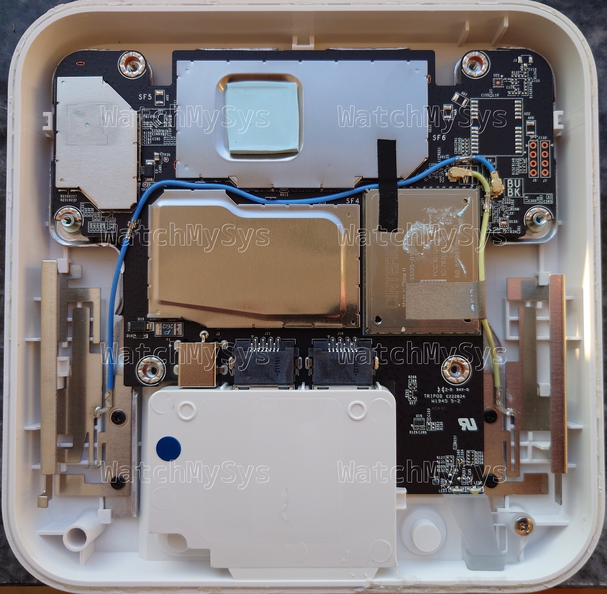
- Cinterion PLAS9-X LTE Cat 6 modem module (LCC, soldered)
- Gigabit Ethernet (x2, QCA8072 PHY)
- Nano-SIM slot
There are no screws holding the MG21 together, the case is glued. As Meraki used glue and not adhesive to hold the MG21 together, heat does not help in opening the device. To open the MG21/MG21E: guitar picks and Isopropyl alcohol are recommended, with a lot of patience.
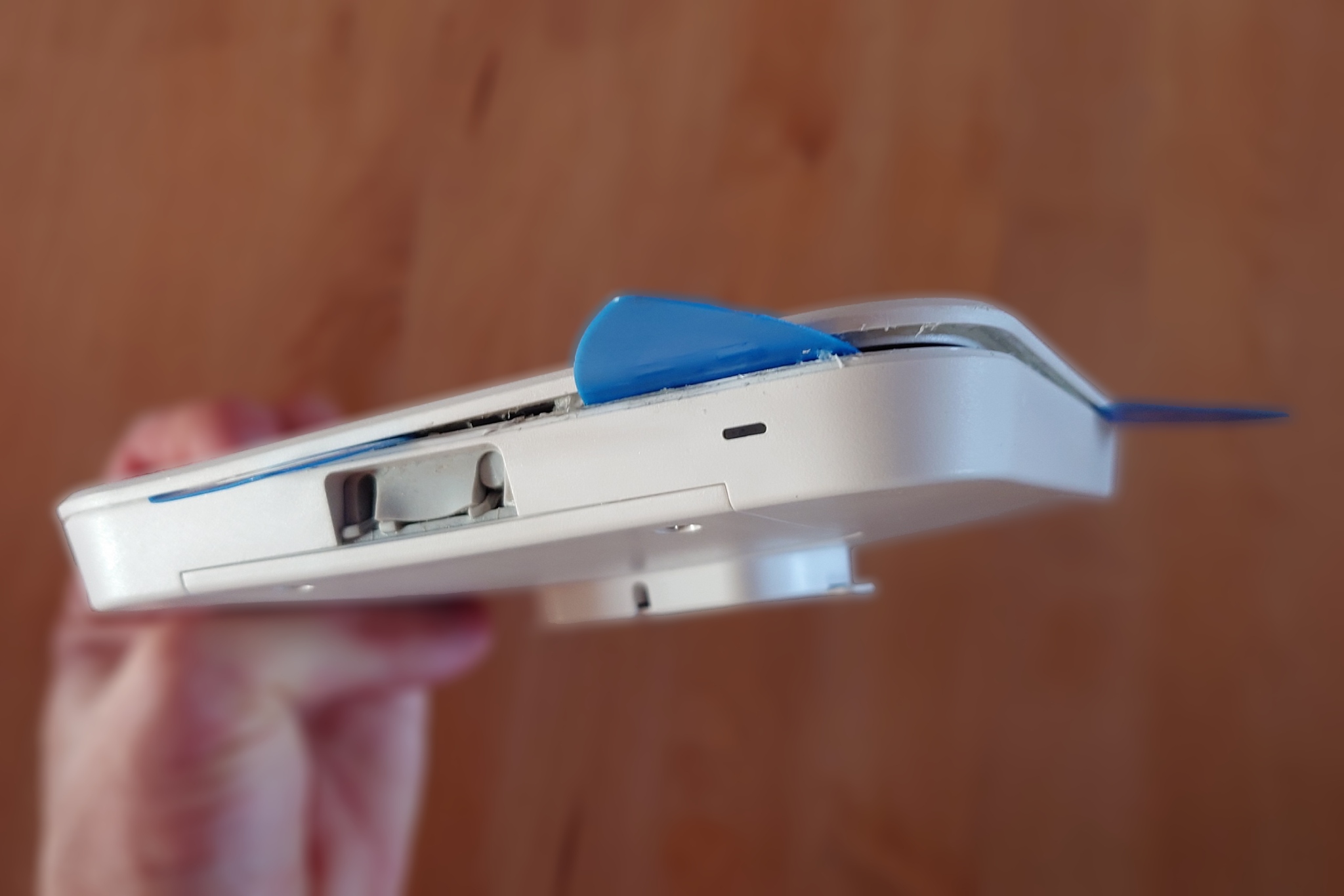
Opening the MG21 with guitar picks and Isopropyl alcohol
The 3.3V UART header in the MG21 is J5, which is unpopulated, and follows the standard Meraki pinout (1: VCC, 2: Tx, 3: Rx, 4: GND) with a 115200 baud rate. It looks like Meraki may have planned to ship the MG21 with an integrated u-blox module (U22), however on my production units the module is absent.
540-00144-01 48RLEQ01.0GA 2019.08.22
With the summary aside, let us focus on the secure boot status of the device. For context, see Breaking secure boot on the Meraki Z3 and Meraki Go GX20.
U-Boot 2017.07-RELEASE-gf49d105aeb-dirty (Jul 13 2020 - 11:22:51 -0700)

DRAM:  242 MiB
machid : 0x8010001
Product: meraki_Tie_Fighter
NAND:  ONFI device found
128 MiB
Using default environment

In:    serial
Out:   serial
Err:   serial
machid: 8010001
ubi0: attaching mtd1
ubi0: scanning is finished
ubi0: attached mtd1 (name "mtd=0", size 112 MiB)
ubi0: PEB size: 131072 bytes (128 KiB), LEB size: 126976 bytes
ubi0: min./max. I/O unit sizes: 2048/2048, sub-page size 2048
ubi0: VID header offset: 2048 (aligned 2048), data offset: 4096
ubi0: good PEBs: 896, bad PEBs: 0, corrupted PEBs: 0
ubi0: user volume: 4, internal volumes: 1, max. volumes count: 128
ubi0: max/mean erase counter: 235/60, WL threshold: 4096, image sequence number: 2046230850
ubi0: available PEBs: 157, total reserved PEBs: 739, PEBs reserved for bad PEB handling: 20


Secure boot enabled.

Read 0 bytes from volume part.safe to 84000000
No size specified -> Using max size (29196288)
Valid image
## Loading kernel from FIT Image at 84000028 ...
Foreshadowing: You will notice that this output is very similar to that of the Z3 and GX20.
Unfortunately changing the EEPROM value to the MR33 (stinkbug) does not work, because Meraki have removed support for the legacy non-secure boot devices from recent U-Boot builds:
U-Boot 2017.07-RELEASE-gf49d105aeb-dirty (Jul 13 2020 - 11:22:51 -0700)

DRAM:  242 MiB
machid : 0x8010001
No product detected! (Major Number 30)
NAND:  ONFI device found
128 MiB
Using default environment

In:    serial
Out:   serial
Err:   serial
machid: 8010001
ubi0: attaching mtd1
(...)

Secure boot enabled.
Removing the BGA NAND and replacing the u-boot region with a dump of the Z3 2018 U-Boot build, U-Boot is still performing signature validation:
U-Boot 2017.07-RELEASE-g39cabb9bf3 (May 24 2018 - 14:07:32 -0700)

DRAM:  242 MiB
machid : 0x8010001
NAND:  ONFI device found
128 MiB
Using default environment

(...)

Secure boot enabled.
The reason for this is that the EEPROM is not found. But why? We have a clue from the stock bootlog of the device:
[   15.287320] i2c /dev entries driver
[   15.302889] at24 0-0056: 8192 byte 24c64 EEPROM, writable, 32 bytes/write
The EEPROM in the MG21 has the address 0x56 instead of 0x50 as on the Z3. This causes the downgraded Z3 U-Boot build to not detect the EEPROM.
The Meraki Go GR10 (Maggot) also has the EEPROM at address 0x56:
struct eeprom_i2c_config
{
	uint16_t gpio_scl;
	uint16_t gpio_scl_func;
	uint16_t gpio_sda;
	uint16_t gpio_sda_func;
	uint16_t eeprom_addr;
};
/* valid eeprom configuration for insects */
static const struct eeprom_i2c_config valid_eeprom_i2c_config[] = {
    { 20, 1, 21, 1, 0x50 }, // Stinkbug, Ladybug, Noisy Cricket
    { 10, 4, 11, 4, 0x56 }, // Maggot
};
However, the GR10 uses different GPIO pins to access the EEPROM.
I do not have the U-Boot source code of the MG21 to review (see endnote). Lacking the U-Boot source code, we can hexdump the Z3 and MG21 U-Boot regions from the flash dumps and compare.
Z3:
00044360  0f 00 14 00 01 00 15 00  01 00 50 00 0a 00 04 00  |..........P.....|
00044370  0b 00 04 00 56 00 00 00  00 f0 f4 a1 ea ea fb 01  |....V...........|
MG21:
000452f0  0f 00 14 00 01 00 15 00  01 00 50 00 14 00 01 00  |..........P.....|
00045300  15 00 01 00 56 00 00 00  00 f0 f4 a1 ea ea fb 01  |....V...........|
Decoding the structs from the hexdump we can infer the C source code used in the MG21 U-Boot build:
static const struct eeprom_i2c_config valid_eeprom_i2c_config[] = {
    { 20, 1, 21, 1, 0x50 }, // Fuzzy Cricket, Fairyfly, Heart of Gold
    { 20, 1, 21, 1, 0x56 }, // Tie Fighter
};
The only difference between the MG21 and Z3 is in the EEPROM address, the GPIO configuration remains the same.
Reviewing the datasheet of the at24 EEPROM, we can see that the address is set by the first 3 pins (A0-A2) being pulled to ground or Vcc. Since the EEPROM has the address 0x56, that must correspond to the bitmask 110 or: A0: 0, A1: Vcc, A2: Vcc.
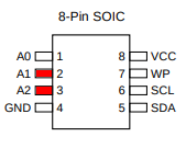
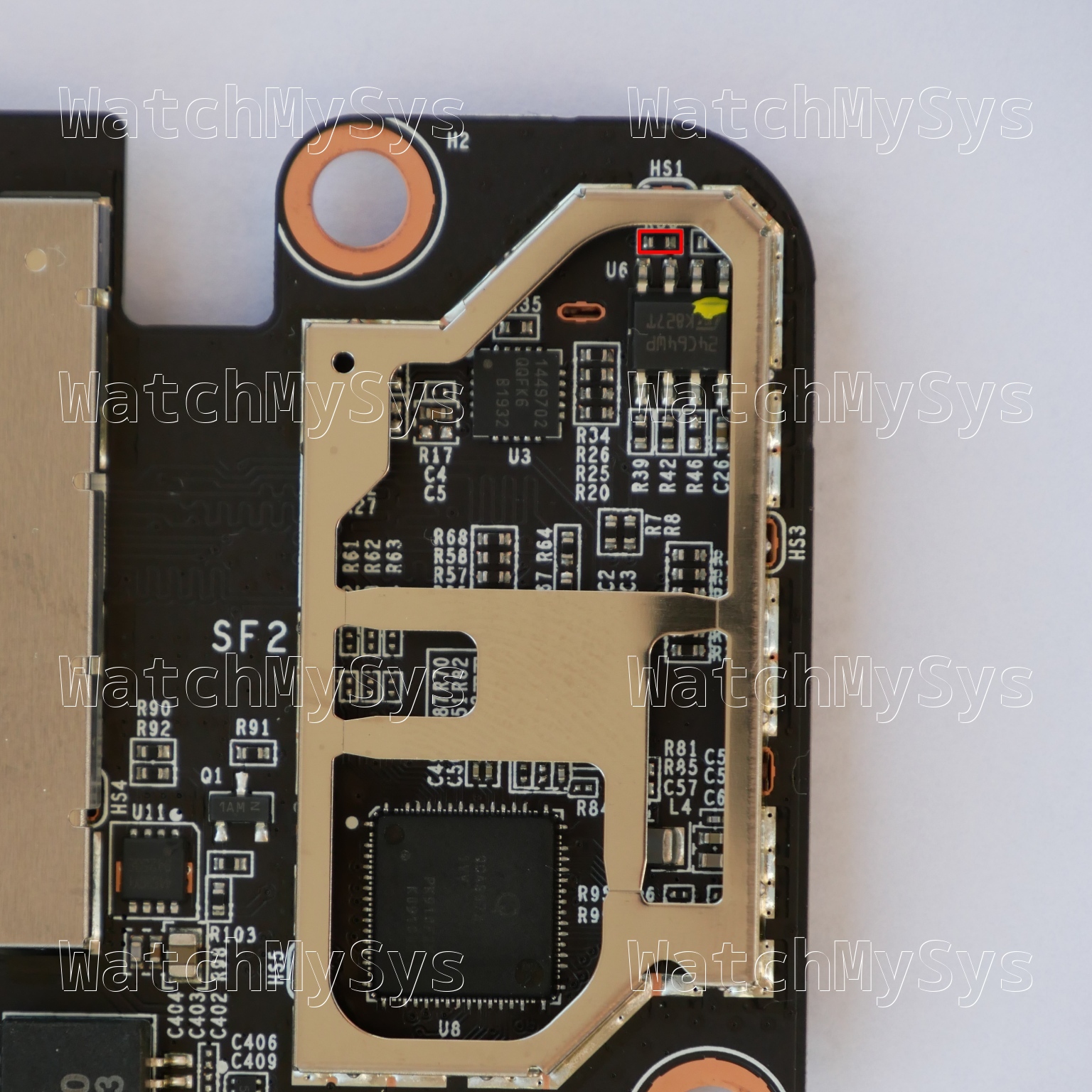
After some verification on the PCB, removing the surface mount resistor R50 (4.7k) above U6 will remove Vcc from A1 and A2, changing the EEPROM address from 0x56 to 0x50.
The signed Z3 2018 U-Boot build now properly detects the EEPROM at address 0x50 and disables signature validation on the payload.
The chain-loaded U-Boot I used as a proof-of-concept is based on the Z3 GPL source code provided by Meraki in 2021, which does not include support for the MG21. Networking is non-functional, which makes further development challenging as images must be (slowly) transferred via UART.
Some readers may be wondering about the MG41. This secure boot bypass does not work on the MG41.
Meraki has signed the MG41 bootloader with a unique device certificate (x-wing), so cross-flashing U-Boot from another device such as the Z3 will not work.
Although the FCC internal photos of the MG41 show both NAND and EMMC, the production MG41 has only EMMC present. The boot_meraki_qca function has been re-written as boot_meraki_mmc_qca. During this re-write, Meraki removed the vulnerable switch statement that aborts enforcing signature validation on legacy products.
tl;dr
- MG21 uses the same device signing certificate as the Z3 and GX20
- Overwrite
u-booton NAND with dump from Z3 running 2018 release - Change Product ID in EEPROM to device without secure boot (MR33)
- Desolder R50 to change EEPROM address
The MG41 is not vulnerable to this technique.
| Model | Meraki Board | Part number |
|---|---|---|
| MG21 | Tie Fighter | 600-89010 |
| MG21E | Tie Fighter | 600-89010 |
| MG41 | X-Wing | 600-119020 |
| MG41E | X-Wing | 600-119010 |
There is still a long road ahead to support the MG21 with any custom firmware such as OpenWrt. Downgrading U-Boot on the device is not easy due to the weather proofing of the device, and the use of BGA NAND.
The GPL source code for the MG21 and MG41 was requested from Meraki in April 2024. At the time of writing Meraki has not provided any of the requested source code.
Meraki announced the end of sale of the MG21 and MG41 in March 2024, and stopped selling the MG21 and MG41 on 2024-09-18.