Following the analysis done by Leo Leung of the Cisco Meraki MS220-8P boot process, I wanted to share more information I’ve uncovered about the firmware source code, layout, and modification.
Cisco were not very forthcoming with the source code, and initially tried to claim that because the product was past the End of Sale, they were under no obligation to provide the source code. I am not a lawyer, but my understanding is that this claim is in violation of GPLv2 Section 3b, which states the the vendor must make the source code available for at least 3 years after the last distribution:
Accompany it with a written offer, valid for at least three years, to give any third party, for a charge no more than your cost of physically performing source distribution, a complete machine-readable copy of the corresponding source code, to be distributed under the terms of Sections 1 and 2 above on a medium customarily used for software interchange
https://opensource.org/licenses/gpl-2.0.php
I am extremely disappointed to see that Cisco is still not forthcoming with GPL source code. They have little to gain by being so difficult, and it is very disappointing to see them claiming they aren’t under obligation to provide the source code due to the product being discontinued.
To save anyone else the trouble of dragging the source code for Meraki Vitesse based switches (MS22, MS42, MS220, MS320) out of Cisco, I have mirrored the source code into 2 repositories on GitHub:
- Stage 1 (NOR bootloader, kernel 3.18.122, includes RedBoot LinuxLoader)
- Stage 2 (NAND firmware, kernel 3.18.123)
Please note: the kernel modules used to control the switch ASIC (vtss_core, merakiclick) are not included in the above source code. If you ever plan to build your own kernel and want to use the switch, you will need to extract the kernel modules corresponding to the above kernel versions from your switch.
My initial attempts to modify the firmware followed Leo’s instructions to disassemble the mtd region boot1. I was perplexed by the contents of the boot1-patched-post data that Leo’s script extracted from the image. The data in this region has an extremely high entropy:
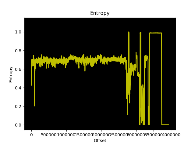
The data is quite large too, approximately 200KB or 5% of the boot1 region. That’s a lot of space to give up on an embedded system for no apparent reason!
I decided to zero out the contents of this boot1-patched-post section and see what effect it would have on the boot process of the switch. The result was a kernel panic, cannot open initrd:
[    2.537000] devtmpfs: error mounting -2
[    2.541000] Warning: unable to open an initial console.
[    2.548000] VFS: Cannot open root device "(null)" or unknown-block(0,0): error -2
[    2.556000] Please append a correct "root=" boot option; here are the available partitions:
[    2.564000] 1f00          131072 mtdblock0  (driver?)
...
[    2.674000] 1f15            2670 mtdblock21  (driver?)
[    2.679000] mkp_lg: VFS: Unable to mount root fs on unknown-block(0,0)
[    2.679000] Kernel panic - not syncing: VFS: Unable to mount root fs on unknown-block(0,0)
So the kernel can no longer find the initramfs, even though the XZ archive is still present in the region. This got me thinking that the region must contain information the kernel uses to extract the XZ compressed initrd.
The build instructions I received from Meraki with the source code stated:
To build OpenWRT firmware:

cd meraki-firmware/openwrt
cp config-elemental-3.18 .config
make oldconfig
make -j1 BOARD=elemental-3.18 OPENWRT_EXTRA_BOARD_SUFFIX=_3.18


To build Linux-3.18 kernel:

cd meraki-firmware/linux-3.18
cp ../openwrt/target/linux/elemental-3.18/config .config
make CROSS_COMPILE=../openwrt/staging_dir_mipsel_nofpu_3.18/bin/mipsel-linux-musl- ARCH=mips oldconfig

make CROSS_COMPILE=../openwrt/staging_dir_mipsel_nofpu_3.18/bin/mipsel-linux-musl- ARCH=mips prepare

touch rootlist
make CROSS_COMPILE=../openwrt/staging_dir_mipsel_nofpu_3.18/bin/mipsel-linux-musl- ARCH=mips vmlinux
After following these instructions and ending up with a vmlinux that was far too big to fit into the flash region, I figured out how to build the kernel such that it fits into the boot region. This also clarified what the contents of boot1-patched-post from Leo’s extraction script contains.
To start, if you are building the 3.18.122 kernel for the SPI flash (first stage boot, before kexec) you absolutely need a rootlist file. For the stock Meraki firmware, I have re-created the contents of the rootlist file:
file /bootsh ramdisk/bootsh 755 0 0
slink /init bootsh 777 0 0
file /kexec ramdisk/kexec 755 0 0
file /MERAKI_BUILD ramdisk/MERAKI_BUILD 755 0 0
dir /bootroot 755 0 0
dir /dev 755 0 0
slink /lib bootroot/lib 777 0 0
slink /etc/ bootroot/etc 777 0 0
slink /usr bootroot/usr 777 0 0
slink /sbin bootroot/sbin 777 0 0
slink /bin bootroot/bin 777 0 0
The Meraki provided instructions produce an ELF vmlinux, which is not what at all what the switch is booting. You must use objcopy to strip vmlinux before you can get it to what the switch expects in the firmware:
mipsel-linux-musl-objcopy -O binary -S vmlinux vmlinux.binBy following the above steps, building the kernel with the above rootlist file contents and stripping vmlinux with objcopy, vmlinux.bin is the data that goes into the boot1 region immediately after the 32 byte header. Pad the header + vmlinux.bin with zeros to ensure it is 3932160 bytes total.
Aside: You’re probably not interested in including the same files in your ramdisk as the stock Meraki firmware. Unless you have modified the NAND image to spawn a console and kill their management daemons, you’ll have the same end result as the stock firmware. However, it is a useful test to ensure that you can build and boot the kernel yourself:
Linux version 3.18.122-meraki-elemental (hmartin@alp) (gcc version 5.4.0 (GCC) ) #4 Sun Mar 1 14:44:24 UTC 2020The meraki_stock branch of the 3.18.122 repository includes the defconfig and rootlist file you need to build the 3.18.122 kernel.
Now onto more useful matters, modifying the bootloader. I grew tired of having CRC errors when testing my changes, so I patched the CRC check out of the bootloader. Later on, I decided I wanted to try booting 3.18.123 directly from NOR, except the stripped vmlinux is nearly 5MB, too large. So I patched out the boundary check in the bootloader. You can find both versions of the bootloader (without CRC and without CRC/boundary check) in the 3.18.122 repository on GitHub.
Meraki appears to supply a common firmware for all their Vitesse based switches. The MS220-8P is based on the luton26 ASIC, while the larger switches (MS22, MS42, MS220-24/48, and MS320-24/48) appear to be based on the Jaguar-1 ASIC. Since you don’t need the kernel modules for other models in the firmware, you can delete them (and other unnecessary Meraki daemons) and fit the entire firmware in roughly 8MB using XZ compressed squashfs.
With this combination, you can boot Linux 3.18.123 from NOR, with a squashfs on NOR:
[ 0.000000] Kernel command line: console=ttyS0,115200 mtdparts=m25p80:0x40000(loader1),0x4c0000(boot1),0x800000(bootubi),0x300000(jffs2) root=/dev/mtdblock3 rootfstype=squashfs ubi.mtd=gen_nand.0 mem=0x7FF0000 ramoops.mem_address=0x7FF0000 ramoops.mem_size=0x10000 ramoops.block_size=0x10000Since the kernel version matches the modules shipped by Meraki in their firmware, you can load the modules required to manage the ASIC:
# lsmod
vc_click 251569 0 - Live 0xc35eb000 (PO)
elts_meraki 4132849 1 vc_click, Live 0xc30ab000 (PO)
merakiclick 1587774 2 vc_click,elts_meraki, Live 0xc2854000 (O)
proclikefs 5189 2 merakiclick, Live 0xc007b000 (O)
vtss_core 663855 1 vc_click, Live 0xc13f0000 (PO)
This approach is not without its own problems. The Meraki firmware expects / to be mounted rw, something that isn’t possible with squashfs.
In summary, with the following components you can boot directly from NOR, without touching NAND at all:
- Modified redboot
- Kernel 3.18.123 (NOR boot, squashfs root)
- Squashfs
- Build scripts
Please understand that I have not solved all the issues with this approach, and above resources are intended as a guide to encourage future development. To illustrate, here is a flashable image (see here) for your MS220-8P that illustrates booting entirely from NOR. Although I would like to caution you that this is a proof of concept, not a functional firmware. If you have any improvements please submit your pull request the meraki-builder repository!
The above information is the product of months of reverse engineering, development, and testing on an MS220-8P. It is my hope that by providing the GPL archive, my modifications, build scripts, and documentation that others will find a more elegant way to run the firmware entirely from NOR, which would significantly decrease the complexity to running a custom firmware on the MS220-8P.
That’s all for now. I will continue working on this project in the background and may have more updates in the future.