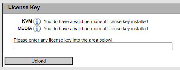
A few years ago we looked at iRMC S4 on the Fujitsu TX140 S2. iRMC S4 provides typical remote management features that you would expect to find in a BMC: remote power control, sensor monitoring and alerting, hardware inventory, and boot order over-ride/selection. Some additional features like the remote KVM and remote media require a license key.
Licensed IPMI features are not new and other vendors, such as Supermicro, have had their IPMI license reverse engineered.
Fujitsu are a somewhat niche vendor when it comes to servers, and to date I am not aware that anyone has publicly reverse engineered the iRMC S4 license.
They say a picture is worth a thousand words, so we will start with a diagram

iRMC S4 license contents
An iRMC S4 license has four distinct fields
- Header/magic: 4 bytes (
iRMC) - Features to be enabled by the license (bitmask): 4 bytes
- Type of license (temporary or permanent): 4 bytes
- CRC32 of the system serial number: 4 bytes
The above data is encrypted using AES-128, and the output is base32 encoded with hyphens every 4 characters.
For example, here is an iRMC S4 license (enabling KVM and remote media) for an RX chassis with the serial number YLNS012345:
ZKAF-Z5EG-PL5G-6GFR-YEG6-CKGM-KQ
And the actual license contents:
69524d43 0300000 0ffffff05 2e4dbb51
Licensed features in iRMC S4 include:
- Remote KVM
- Remote media
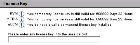
- eLCM
Feature bit 1 is for KVM, bit 2 remote media, and bit 3 seems to be for eLCM (eLCM appears to only be available on some models).
Installing an iRMC S4 license on a TX chassis
Back in 2014, Fujitsu changed the iRMC S4 licensing to be “node-locked”, which means that a license is tied to a specific server and cannot be transferred. The installation of a volume license is not possible after 2015-01-01 00:00:00.
iRMC S4 tracks the “Power on Hours (PoH)” of the chassis, and it appears that there is the capability to generate a temporary license which will expire after a certain number of Power on Hours is reached, probably to provide customers with time to evaluate the value proposition of purchasing iRMC licenses.
iRMC S4 time limited license
If you are reading this, then you are probably not interested in generating temporary licenses. Setting the field to 0xffffff00 for a TX chassis and 0xffffff05 for an RX chassis will result in a permanent license.
Now that we have covered the fields in an unencrypted iRMC S4 license, it will be obvious that the example license ZKAF-Z5EG-PL5G-6GFR-YEG6-CKGM-KQ is not simply the base32 encoded binary license data.
Unlike Supermicro, Fujitsu use a static HMAC message and key to create an HMAC-SHA1 hash, the first 16 bytes of which are used as the key for AES-128. The AES encrypted data is then base32 encoded and the output is the iRMC license you install via the web interface.
I will not be disclosing Fujitsu’s HMAC key and AES IV here, but suffice to say you can download and unpack the iRMC firmware from Fujitsu and find the values in /usr/local/lib/libfts_license.so.1.12.1. Thanks Fujitsu!
For anyone interested in reverse engineering the iRMC S4 license validation themselves:
- the HMAC key and message are used in
lkeyInitCipherKeyinlibfts_license - the AES IV is used in
decrypt_with_licenseinlibfts_license
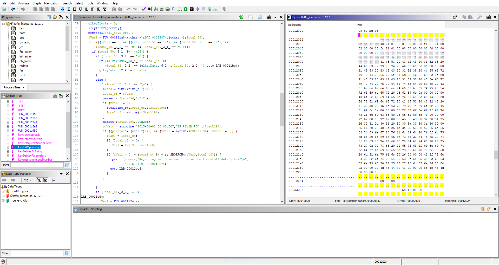
libfts_license in Ghidra, showing decompiled function and hexdump
Anyone looking for a simpler solution, a proof-of-concept for python is here. Note that you need to provide the correct HMAC/AES values obtained from libfts_license, you do not need Ghidra for this, you can do it with a simple hexdump utility.
If you want to investigate the exported license (using “iRMC S4” -> “Save Configuration” -> “Include License Information”), here is a validation script.
To anyone wondering, the license logic from iRMC S4 is not applicable to older iRMC platforms such as iRMC S2 or iRMC S3.
However, the license logic appears to be unchanged between iRMC S4 and S5. Hardware with iRMC S5 is too expensive to justify purchasing to verify this, but maybe someone will leave a comment as to whether the license logic described here is still applicable to iRMC S5.
Edit: An anonymous reader has written to say that the logic is unchanged for iRMC S5/S6 ✨