The last time we looked at the Cisco Meraki MS220, it was possible to boot kernel 3.18.123 compiled from the Cisco GPL archive. The ability to compile the kernel, with our own command line and modules opened up new possibilities for firmware modification.
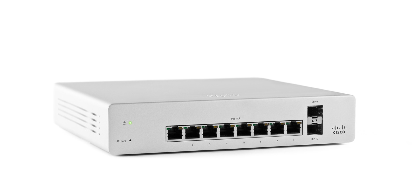
That was a very good start, but there is more improvement possible. Support for the Microsemi VCore III SoCs was added to u-boot in late 2018. The MS220-8P contains the Luton26 SoC, but with only 10 ports. The MS220-8P appears to follow the Microsemi PCB090 reference design, and it is possible to build and boot u-boot (v2019.10):
U-Boot 2019.10 (Apr 04 2020 - 09:26:23 +0000)

MSCC VCore-III MIPS 24Kec
Model: Luton26 PCB090 Reference Board
DRAM:  128 MiB
Loading Environment from SPI Flash... SF: Detected mx25l12805d with page size 256 Bytes, erase size 64 KiB, total 16 MiB
OK
In:    serial@10100000
Out:   serial@10100000
Err:   serial@10100000
Net:   Could not get PHY for miim-bus1: addr 0
Could not get PHY for miim-bus1: addr 1
Could not get PHY for miim-bus1: addr 2
Could not get PHY for miim-bus1: addr 3
Could not get PHY for miim-bus1: addr 4
Could not get PHY for miim-bus1: addr 5
Could not get PHY for miim-bus1: addr 6
Could not get PHY for miim-bus1: addr 7
Could not get PHY for miim-bus1: addr 8
Could not get PHY for miim-bus1: addr 9
Could not get PHY for miim-bus1: addr 10
Could not get PHY for miim-bus1: addr 11

Warning: switch@1010000 (eth0) using random MAC address - 62:bf:42:f4:e4:5f
eth0: switch@1010000
Hit any key to stop autoboot:  0
luton #
u-boot for the Luton26 specifies the environment to be saved at 1MB. This does not match my desired flash layout, so I redefined the ENV_OFFSET and associated variables in board/mscc/luton/Kconfig:
# 64KiB
config ENV_SECT_SIZE
        default 0x10000
# 128KiB at 512KiB
config ENV_SIZE
        default 0x20000
# at 512KiB
config ENV_OFFSET
        default 0x80000 if ENV_IS_IN_SPI_FLASH
Though for some reason this is not working as anticipated, and the environment is still corrupted after saveenv (╯°□°)╯︵ ┻━┻
With u-boot, I was finally able to test booting a compressed kernel. I wonder why Meraki is not compressing the kernel, since compression does not appear to slow down boot at all, and the compressed kernel is much smaller than an uncompressed kernel. Using xz compression, the 3.18.123 kernel is ~2MB, instead of ~5MB. Some fairly trivial modifications were necessary to achieve this.
With u-boot support, testing is much easier. u-boot has network support on the Luton26, making it possible to tftpboot a kernel. This vastly increases the speed of testing as you don’t have to write the kernel to SPI flash before testing changes.
Getting the handoff between u-boot and the kernel for the command line was difficult to figure out. The original bootloader, Redboot, doesn’t have the kernel command line built-in the command line is always compiled into the kernel. In that context, it’s logical why Vitesse didn’t include support for reading the bootloader command line in the kernel (and why Cisco didn’t modify the kernel to include support, since they’re shipping Redboot in these switches).
u-boot was placing the variables somewhere in RAM, but for some reason the kernel wasn’t getting them in its boot command line. u-boot has a humorously titled page on exactly this issue: Linux Kernel Ignores my bootargs. After digging through the u-boot source, it was clear that argv are being passed at the start of DRAM at 0x80000000:
in include/configs/vcoreiii.h:
#define CONFIG_SYS_SDRAM_BASE           0x80000000
in board/mscc/luton/luton.c:
gd->bd->bi_boot_params = CONFIG_SYS_SDRAM_BASE;
After much searching through the 3.18.123 kernel source code, it became clear that prom is typically where the boot args receiving code is typically placed, so I took inspiration from the lantiq prom code to copy the bootloader argc and argv.
Now, it’s possible to tftpboot compressed kernels with boot args!
Except… there is no serial output from userspace. printk messages are displayed on serial, but no userspace programs (e.g. init) seem able to print out /dev/ttyS0 when using u-boot.
Compiling the kernel with /dev/ttyprintk support and adding custom scripts in /etc/init.d shows that userspace is indeed alive:
[    4.779000] [U] S05printk starting; userspace is alive
[    5.689000] random: dropbear urandom read with 85 bits of entropy available
[    7.356000] [U] Hello from S51printk; userspace is alive but serial is broken
/dev/ttyS0 seems normal, and the memory map is the same as RedBoot (which is logical, since it’s the same kernel version):
[    7.706000] [U] S99 starting; we print stuff
[    7.712000] [U] Now we print /dev
...
[    8.150000] [U] crw-------    1 root     root        4,  64 Jan  1 00:00 ttyS0
[    8.159000] [U] crw-------    1 root     root        5,   3 Jan  1 00:00 ttyprintk
[    8.207000] [U] Now we print /proc/iomem
[    8.222000] [U] 00000000-07feffff : System RAM
[    8.227000] [U]   00000000-00000000 : Crash kernel
[    8.232000] [U]   00100000-0048cc83 : Kernel code
[    8.237000] [U]   0048cc84-0057610f : Kernel data
[    8.241000] [U] 40000000-4fffffff : Serial interface
[    8.247000] [U] 50000000-5fffffff : Parallel interface
[    8.252000] [U]   50000000-50000010 : gen_nand.0
[    8.256000] [U]     50000000-50000010 : gen_nand.0
[    8.261000] [U] 60000000-60ffffff : Switch registers
[    8.266000] [U] 70000000-701fffff : CPU Registers
[    8.271000] [U]   70100000-7010001f : serial
[    8.279000] [U] Now we print /proc/vmallocinfo
[    8.294000] [U] 0xc0000000-0xc1001000 16781312 __ioremap+0x128/0x4ac ioremap
[    8.301000] [U] 0xc1004000-0xc1009000   20480 jffs2_lzo_init+0x18/0x84 pages=4 vmalloc
[    8.309000] [U] 0xc1009000-0xc100c000   12288 jffs2_lzo_init+0x24/0x84 pages=2 vmalloc
[    8.317000] [U] 0xc100c000-0xc100e000    8192 __ioremap+0x128/0x4ac ioremap
[    8.324000] [U] 0xc100e000-0xc1010000    8192 __ioremap+0x128/0x4ac ioremap
[    8.331000] [U] 0xc1010000-0xc1035000  151552 deflate_init+0x44/0xf8 pages=36 vmalloc
[    8.339000] [U] 0xc1035000-0xc1041000   49152 deflate_init+0x98/0xf8 pages=11 vmalloc
[    8.347000] [U] 0xc1041000-0xc1045000   16384 n_tty_open+0x2c/0x14c pages=3 vmalloc
[    8.355000] [U] 0xc1045000-0xc1066000  135168 xz_dec_lzma2_create+0x54/0x9c pages=32 vmalloc
[    8.363000] [U] 0xc1080000-0xc1281000 2101248 __ioremap+0x128/0x4ac ioremap
[    8.370000] [U] 0xc1285000-0xc1289000   16384 n_tty_open+0x2c/0x14c pages=3 vmalloc
[   97.943000] random: nonblocking pool is initialized
I haven’t solved the issue yet of why serial output is broken in userspace 😔
If anyone has experienced broken serial in userspace but not for kernel printk, I’d love to hear how you resolved the problem!