I received an innocent sounding question via GitHub, would the custom firmware I have been developing for the MS220 work on an MS120?
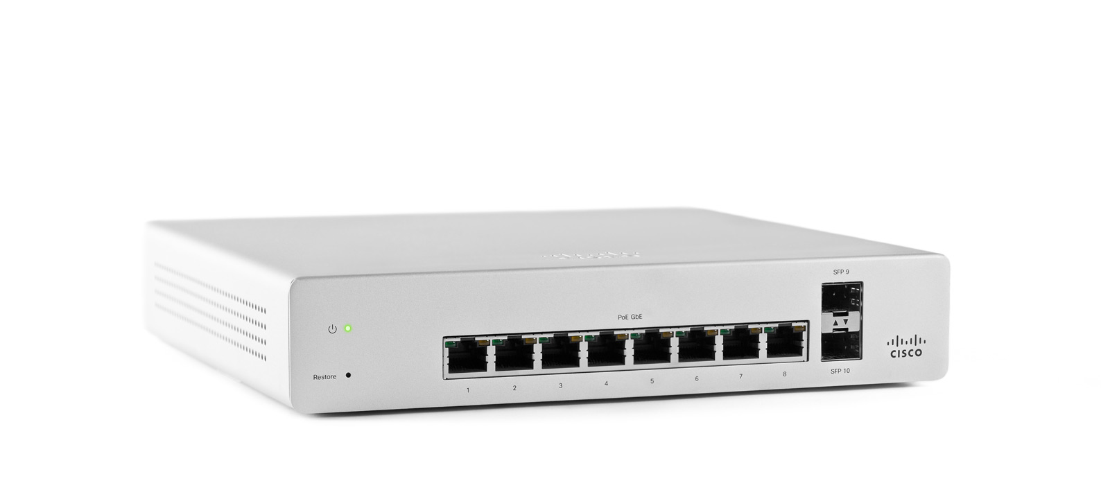
I am an eternal sucker for good mysteries involving hardware, so I found a seller on eBay offering an MS120-8-HW for $95 USD (plus shipping and customs to the EU). A few weeks of buyer’s remorse and waiting, and I had the MS120 in my hands.
One thing that immediately struck me about the MS120 is the material change from aluminum to steel. While I thought Meraki’s use of anodized aluminum in the MS220 series was a silly choice for the larger rack mounted models, it did make me think they were attempting to position themselves as the Apple Computer of networking products (“You pay the premium because we’re different”). Regardless of their intentions with the aluminum MS220 series, it was a precedent and it cheapens the experience to see them swap out aluminum for steel.
Let us continue, because whinging about metal choices is not bringing us closer to answering the original question.
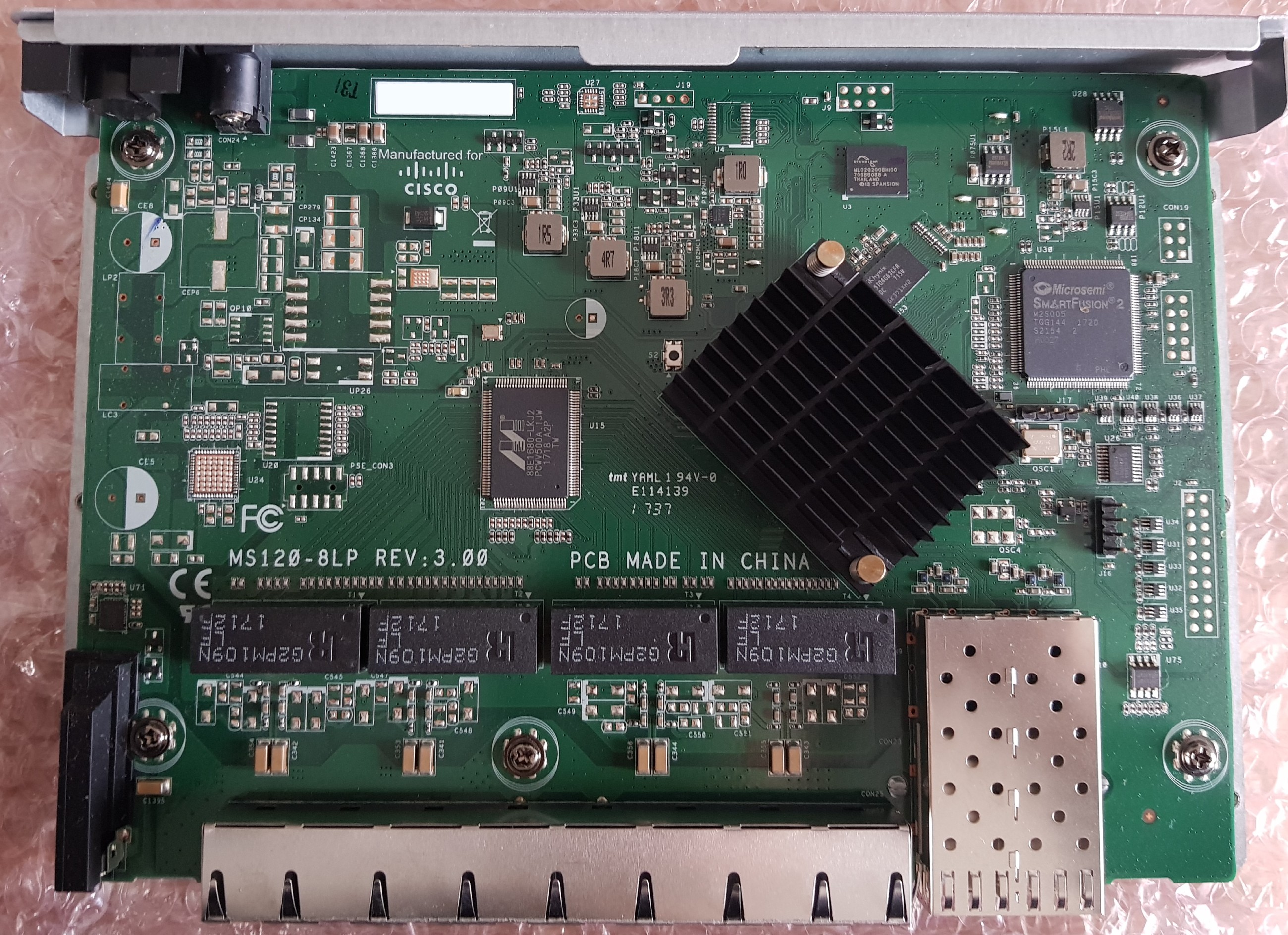
Inside the MS120-8-HW
The MS120 is based on the Marvell Alleycat3 platform, referred to as kelpie-8 in the u-boot source and otherwise known by its marketing name “Prestera.” It is an ARMv7 core running at 400MHz with 512MB of DDR3 and 256MB of NAND flash.
The UART header is J16 at 115200n8 with the pinout:
- Vcc (Do not connect)
- Rx
- Tx
- GND
Pin 1 is closest to the SFP cage.
J17 is a mystery jumper. I have not identified its purpose yet.
There is 32Mbit (4MB) of SPI flash present, however as far as I can tell, this is connected directly to the Microsemi SmartFusion 2 and not to the Marvell ASIC. Using a hardware reader and a chip clip, I dumped the contents to examine it. Running binwalk yielded no results.
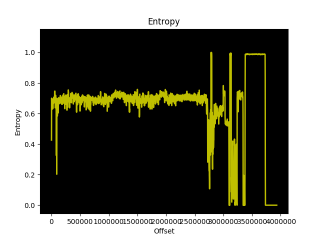
The entropy graph of the dump suggests that there are multiple copies of the same data stored, which follows Meraki’s design with the MS220 switches where there are primary and backup copies of the bootloader.
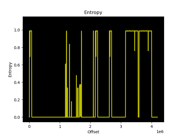
Entropy graph of the 32Mbit flash in the MS120
Further inspection confirms that there are two identical copies of what I think is u-boot stored in the flash, starting at 0x301000. Each copy is approximately 420KB, which would correspond to the size of u-boot for this platform. However, the entropy is much higher than the entropy of u-boot.bin built using the Meraki GPL source, and contains only one readable string: kelpie_top
Perhaps this is the output of u-boot after running doimage to enable Secure Boot and AES-128 encryption?
The PCB traces from the winbond flash appear to go directly to the SmartFusion 2, but the u-boot UART output shows that the BootROM is booting from SPI:
BootROM 1.41
Booting from SPI flash
Is the SmartFusion 2 emulating an SPI device to the Alleycat3 after verifying the integrity of the u-boot binary in ROM?
u-boot then executes an application at memory address 0x0C100000 that prints the value of multiple “SecureBoot Registers” the strings of which do not appear anywhere in the u-boot code provided in the GPL archive:
## Starting application at 0x0C100000 ...

----Security Versions----
SecureBoot: R03.11b39af022017-07-25
SB Core: F01114R18.1680555472017-07-12
Microloader: MG0008R01.0103302017

----SecureBoot Registers----
system_invalid: 0
boot_check_count_error: 0
boot_done: 1
boot_ok: 1
boot_check_count_golden: 0
boot_check_count_upgrade: 2
boot_status_golden: 0
boot_status_upgrade: 1
first_bootloader: 1

----Upgrade----
boot_error: 0
boot_check_count_error_vc: 0
boot_check_count_error: 0
boot_timeout_vc: 0
boot_timeout: 0
boot_cs_good: 1
boot_config_error: 0
boot_version_error: 0
boot_config_error_code: 0
boot_error_code: 0
boot_cs_good: 1
boot_version_error: 0
boot1_cs_key_type: 1
boot1_cs_return_code: 0
boot1_cs_key_index: 5
boot2_cs_return_code: 0
boot2_cs_key_index: 5
boot2_cs_key_type: 1

----Other Registers----
fpga_version: 001b
Meraki do not include the build toolchain in their GPL archive. Luckily, I remembered that I have encountered this Marvell fork of u-boot before, for the Western Digital EX2100 which also uses a Marvell Armada 385 from the same family of ARMv7 CPU cores. Western Digital does include the Marvell toolchain used to compile u-boot in their GPL archive, good guy Western Digital!
To save anyone else the effort of setting up a development environment with an ancient version of GCC, I have created a Dockerfile that will handle building u-boot using the Marvell toolchain. You can find this work on GitHub.
I reached out to members of the Doozan forum who have been building Linux images for Marvell based NAS devices for many years to see if they had any more information about Secure Boot. Apparently Marvell CPUs will always kwboot before loading from other sources such as SPI or NAND:
Even if a box has secure boot in stock FW (u-boot, kernel,..), you should be able to kwboot it with a non-secure u-boot/spl binary.
I tried to kwboot the MS120 (with and without the Armada patches), but was unable to get it working. For some reason, the BootROM output is printed twice when kwboot is running, which I have not witnessed during any normal boot sequence:
$ ./kwboot -b u-boot.uart -f -t -B 115200 /dev/ttyUSB0
Sending boot message. Please reboot the target.../
BootROM 1.41
Pattern detected on UART-
BootROM 1.41
Pattern detected on UART/
uart.bin was created using tools/marvell/doimage:
$ ./doimage -T uart -D 0x0 -E 0x0 u-boot.bin u-boot.uart
Unfortunately, this investigation leaves us with more questions than answers.
- What is the contents of the 32Mbit SPI flash?
- Does the SmartFusion 2 only provide glue logic, or does it also protect/verify the contents of SPI flash?
- Why won’t the Alleycat3 kwboot?
- Is the duplicate output from BootROM when kwboot is invoked a clue?
- What is the purpose of the header
J17? - Why did Meraki switch from aluminum to steel?
The MS120 series is a completely different platform from the previous MS220 series, which used Vitesse ASICs with a MIPS core, 128MB of DDR2, 16MB of SPI, and 128MB of NAND flash.
The use of Secure Boot will complicate efforts to create a third-party firmware for the MS120 series. However, the more immediate issue is that kwboot does not work and there is no obvious copy of u-boot in SPI flash we can modify to alter the boot process.