Asus PN50 4700U review

The Asus PN50 is a NUC-sized mini PC based on AMD’s Renoir mobile platform. The PN50 is available in four configurations ranging from a Ryzen 3 4300U (4C/4T) to Ryzen 7 4800U (8C/16T).

I am not made of money and the 4800U commands an extreme premium for less than extreme additional performance over the 4700U (8C/8T), so I ordered the 4700U. I pre-ordered the 4700U in August for 370£ (408€) from Amazon UK (EU prices were 🤪).

Due to reasons which were never well communicated by Asus or Amazon, the release date of the product was delayed several times from early September 2020 until mid-October 2020.


tl;dr – The PN50 with the Ryzen 7 4700U offers a lot of computing power for the size and power budget, and offers a healthy amount of IO. If you are in the market for a NUC-sized PC, you would be remiss if you did not consider the PN50. The 4700U offers impressive performance, beating an i9-8950HK at one third the power.


The PN50 is sold as a barebones system, although some retailers offer it as a bundle with RAM and an SSD if you prefer overpaying for someone else installing 3 socketed components.

In the box:

  • Asus PN50
  • 19V power supply (65W for 4300/4500U, 90W for 4700/4800U)
  • IEC 60320 “mickey mouse” power cable
  • VESA mount
  • Screws for mounting the 2.5″ hard drive, M.2 SSD, and VESA mount
  • User’s guide and driver CDROM

Typical reviews are full of benchmarks (both CPU and GPU), but I want to provide my own perspective on the system so the benchmark section will be brief.

Renoir eats Intel’s mobile offers for lunch. The newest Intel system I have access to is an XPS 15 (9570) laptop with an Intel Core i9-8950HK.

Ryzen 7 4700U (Asus PN50) versus Intel Core i9-8950HK (XPS 15″ 9570)

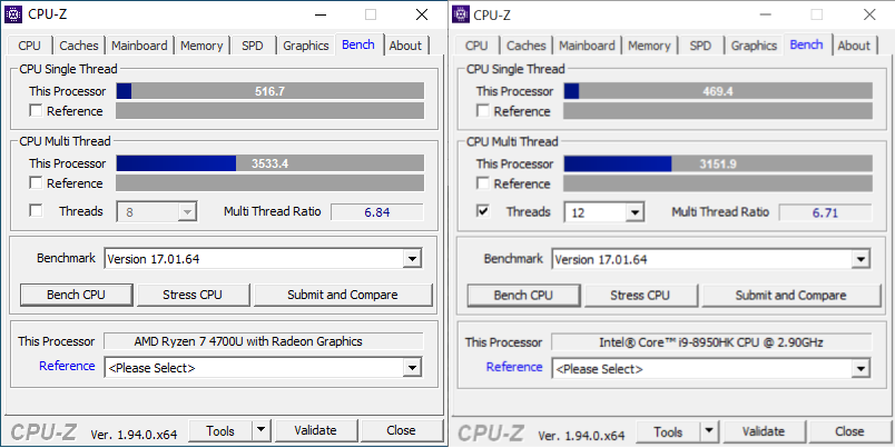
The PN50 with Ryzen 7 4700U scores 10% higher in single-threaded performance and 12% higher in multi-core performance. The 8950HK is not the latest from Intel, but it’s still incredibly impressive that the Ryzen 7 4700U delivers superior performance at one third the power (i9-8950HK: 45W TDP; Ryzen 7 4700U: 15W TDP).


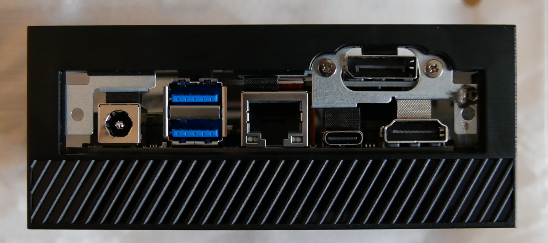
Looking at the internals of the Asus PN50, it seems that the configurable port that Asus offers on the rear is achieved by the use of a ribbon cable to a daughterboard:

DisplayPort daughterboard in the Asus PN50

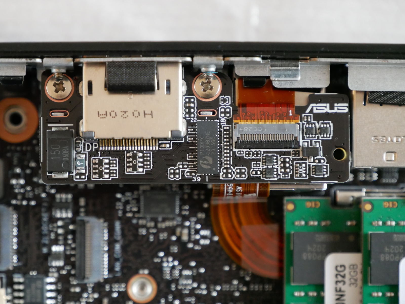
On all retail units that I have seen for sale thus far, the port is configured as a full size DisplayPort. The Asus website shows DisplayPort, RS-232, VGA, and RJ-45 options under the configurable port. I don’t know if Asus ever plans to sell the FPC and daughterboards separately or if they will only be available as BTO options.

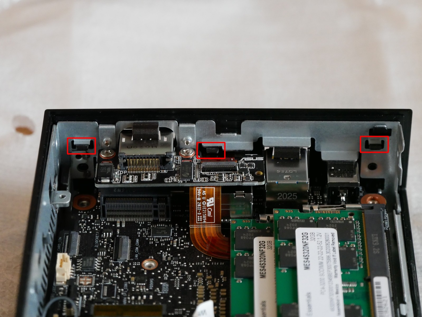
There is an FPC connector present for the secondary network (or RS-232) interface, as well as another FPC connector present for an M.2 carrier (though it isn’t clear what interface the M.2 card would use):

Unused FPC connectors for secondary LAN and M.2 card

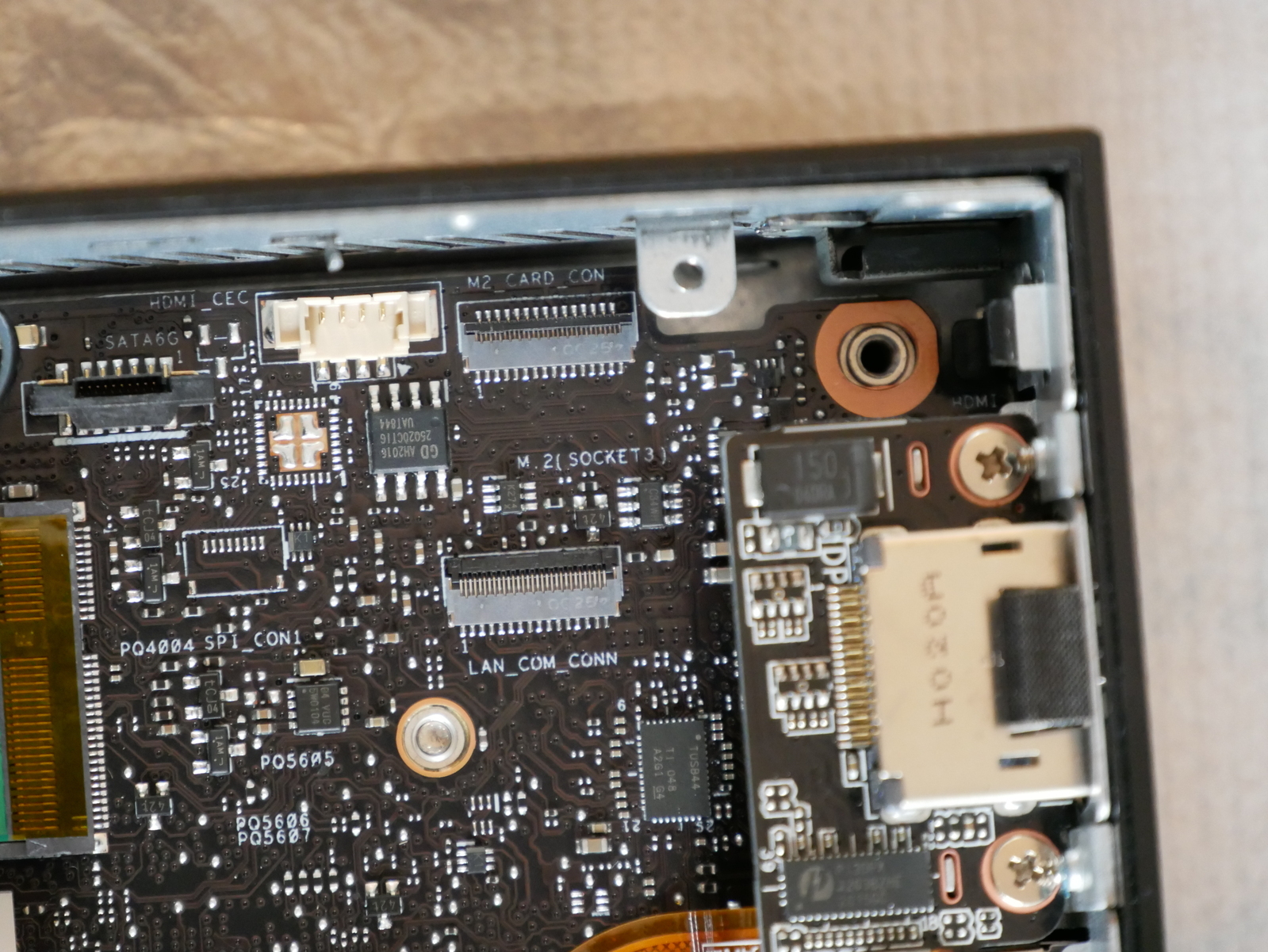
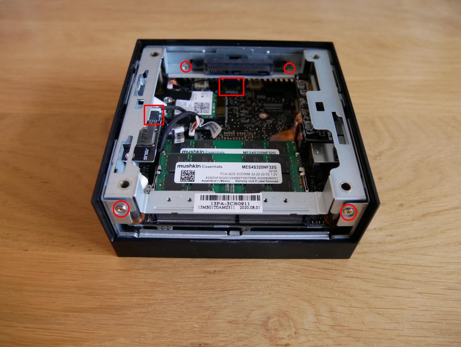
Removing the metal guide for the bottom of the internal chassis is simple, only 4 Philips screws, and two cables (one for 2.5″ SATA connector and one for the micro SD reader):

Removing the bottom of the internal chassis is straightforward

Removing the plastic rear IO shield is also easily accomplished, as there are only 6 plastic retention clips and only 3 need to be released to remove it:

Clips to remove the plastic rear IO shield
Rear view of the PN50 with plastic IO shield removed

Unfortunately, I was unable to determine how you remove the motherboard from the chassis.


Here is the output of lspci with an NVMe SSD installed:

00:00.0 Host bridge: Advanced Micro Devices, Inc. [AMD] Renoir Root Complex
00:00.2 IOMMU: Advanced Micro Devices, Inc. [AMD] Renoir IOMMU
00:01.0 Host bridge: Advanced Micro Devices, Inc. [AMD] Renoir PCIe Dummy Host Bridge
00:01.2 PCI bridge: Advanced Micro Devices, Inc. [AMD] Renoir PCIe GPP Bridge
00:02.0 Host bridge: Advanced Micro Devices, Inc. [AMD] Renoir PCIe Dummy Host Bridge
00:02.1 PCI bridge: Advanced Micro Devices, Inc. [AMD] Renoir PCIe GPP Bridge
00:02.2 PCI bridge: Advanced Micro Devices, Inc. [AMD] Renoir PCIe GPP Bridge
00:02.3 PCI bridge: Advanced Micro Devices, Inc. [AMD] Renoir PCIe GPP Bridge
00:08.0 Host bridge: Advanced Micro Devices, Inc. [AMD] Renoir PCIe Dummy Host Bridge
00:08.1 PCI bridge: Advanced Micro Devices, Inc. [AMD] Renoir Internal PCIe GPP Bridge to Bus
00:08.2 PCI bridge: Advanced Micro Devices, Inc. [AMD] Renoir Internal PCIe GPP Bridge to Bus
00:14.0 SMBus: Advanced Micro Devices, Inc. [AMD] FCH SMBus Controller (rev 51)
00:14.3 ISA bridge: Advanced Micro Devices, Inc. [AMD] FCH LPC Bridge (rev 51)
00:18.0 Host bridge: Advanced Micro Devices, Inc. [AMD] Renoir Device 24: Function 0
00:18.1 Host bridge: Advanced Micro Devices, Inc. [AMD] Renoir Device 24: Function 1
00:18.2 Host bridge: Advanced Micro Devices, Inc. [AMD] Renoir Device 24: Function 2
00:18.3 Host bridge: Advanced Micro Devices, Inc. [AMD] Renoir Device 24: Function 3
00:18.4 Host bridge: Advanced Micro Devices, Inc. [AMD] Renoir Device 24: Function 4
00:18.5 Host bridge: Advanced Micro Devices, Inc. [AMD] Renoir Device 24: Function 5
00:18.6 Host bridge: Advanced Micro Devices, Inc. [AMD] Renoir Device 24: Function 6
00:18.7 Host bridge: Advanced Micro Devices, Inc. [AMD] Renoir Device 24: Function 7
01:00.0 USB controller: ASMedia Technology Inc. ASM1042A USB 3.0 Host Controller
02:00.0 Ethernet controller: Realtek Semiconductor Co., Ltd. RTL8111/8168/8411 PCI Express Gigabit Ethernet Controller (rev 0e)
02:00.1 Serial controller: Realtek Semiconductor Co., Ltd. Device 816a (rev 0e)
02:00.2 Serial controller: Realtek Semiconductor Co., Ltd. Device 816b (rev 0e)
02:00.3 IPMI Interface: Realtek Semiconductor Co., Ltd. Device 816c (rev 0e)
02:00.4 USB controller: Realtek Semiconductor Co., Ltd. Device 816d (rev 0e)
03:00.0 Network controller: Intel Corporation Wi-Fi 6 AX200 (rev 1a)
04:00.0 Non-Volatile memory controller: Samsung Electronics Co Ltd NVMe SSD Controller SM981/PM981/PM983
05:00.0 VGA compatible controller: Advanced Micro Devices, Inc. [AMD/ATI] Renoir (rev c2)
05:00.1 Audio device: Advanced Micro Devices, Inc. [AMD/ATI] Device 1637
05:00.2 Encryption controller: Advanced Micro Devices, Inc. [AMD] Family 17h (Models 10h-1fh) Platform Security Processor
05:00.3 USB controller: Advanced Micro Devices, Inc. [AMD] Renoir USB 3.1
05:00.4 USB controller: Advanced Micro Devices, Inc. [AMD] Renoir USB 3.1
05:00.5 Multimedia controller: Advanced Micro Devices, Inc. [AMD] Raven/Raven2/FireFlight/Renoir Audio Processor (rev 01)
05:00.6 Audio device: Advanced Micro Devices, Inc. [AMD] Family 17h (Models 10h-1fh) HD Audio Controller
05:00.7 Signal processing controller: Advanced Micro Devices, Inc. [AMD] Raven/Raven2/Renoir Sensor Fusion Hub
06:00.0 SATA controller: Advanced Micro Devices, Inc. [AMD] FCH SATA Controller [AHCI mode] (rev 81)
06:00.1 SATA controller: Advanced Micro Devices, Inc. [AMD] FCH SATA Controller [AHCI mode] (rev 81)

Here is the output of lsusb:

Bus 006 Device 001: ID 1d6b:0003 Linux Foundation 3.0 root hub
Bus 005 Device 003: ID 8087:0029 Intel Corp. 
Bus 005 Device 001: ID 1d6b:0002 Linux Foundation 2.0 root hub
Bus 004 Device 001: ID 1d6b:0003 Linux Foundation 3.0 root hub
Bus 003 Device 003: ID 0bda:0129 Realtek Semiconductor Corp. RTS5129 Card Reader Controller
Bus 003 Device 001: ID 1d6b:0002 Linux Foundation 2.0 root hub
Bus 002 Device 001: ID 1d6b:0003 Linux Foundation 3.0 root hub
Bus 001 Device 001: ID 1d6b:0002 Linux Foundation 2.0 root hub

Unfortunately the micro SDXC card reader is only connected via USB 2.0, and the maximum read speed I was able to obtain using a UHS-1 class card was 41MB/s.

This is disappointing as UHS SD cards are frequently capable of read speeds in excess of 100MB/s and Asus appears to have cost-optimized the SDXC card reader here by going with an older USB2.0 design.


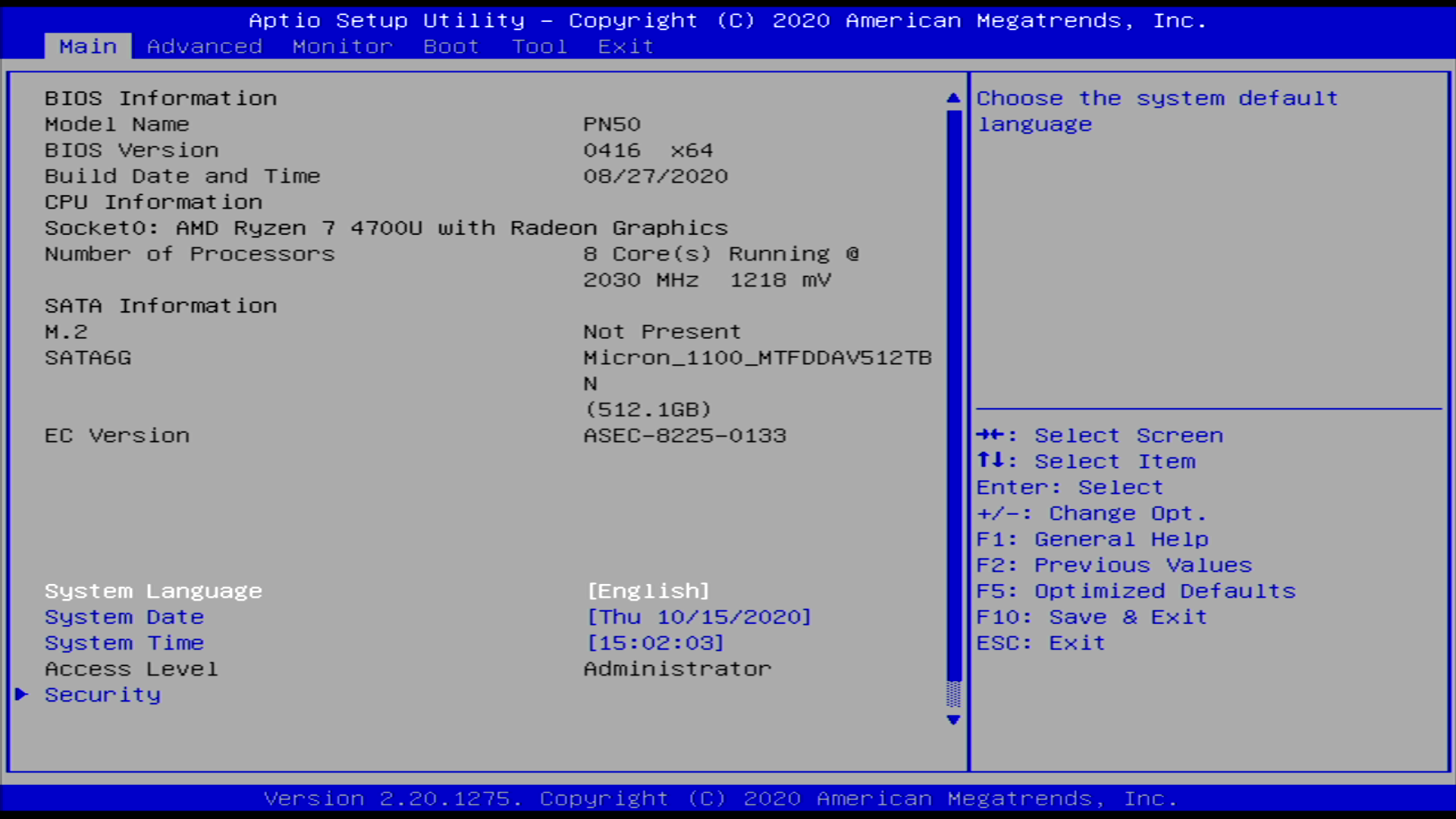
I will give a brief overview of the BIOS, but suffice to say it’s pretty basic with no advanced functionality. But first, the pretty Asus splash screen:

Much incredible, so Renoir

The Main summary is quite basic, and seems to have a bug where the M.2 SSD is shown as Not Present even when installed. The bug is present in both 0409 and 0416 releases.

Summary screen of Asus PN50 0416 BIOS

Despite the Main page stating Not Present, an installed NVMe device is visible under Advanced > NVMe Configuration

The Monitor view offers a summary of system temperatures, CPU Vcore, and fan speed. You can select the fan profile as well.

NVMe temperature is present here ¯\_(ツ)_/¯

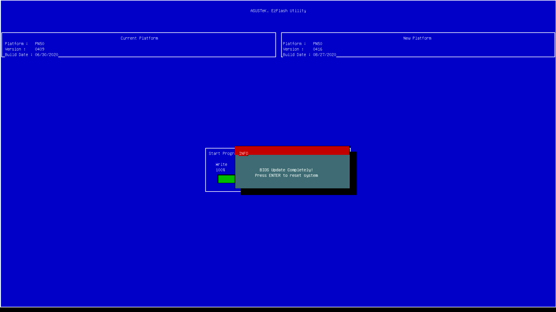
The included EzFlash utility makes updating firmware easy, simply extract the ZIP archive containing the firmware update and put the CAP file on a FAT formatted USB device.

EzFlash: Select the update file from your USB device
Updating the firmware requires a few minutes but is otherwise painless

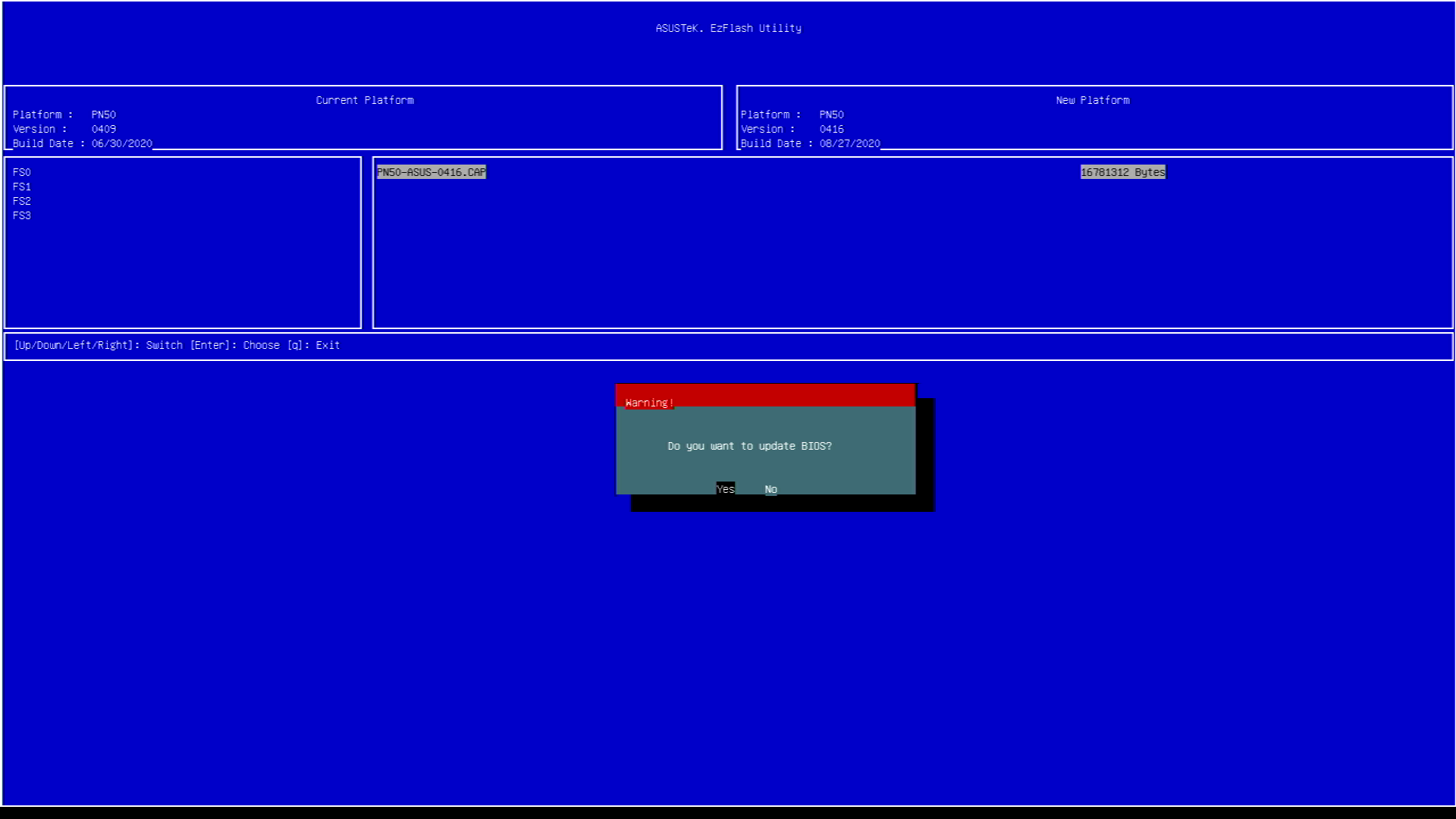
There seems to be a bug where you are prompted to save settings before entering the utility, and selecting No prevents you from entering EzFlash.

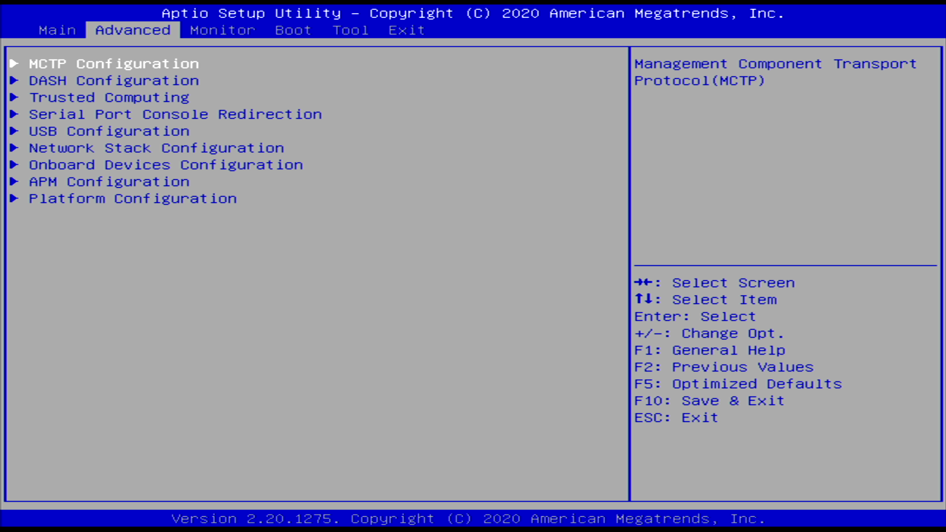
MCTP Configuration, DASH Configuration, and Serial Port Console Redirection are all options added in BIOS 0416 that were not present in BIOS 0409.

Advanced menu of BIOS 0416

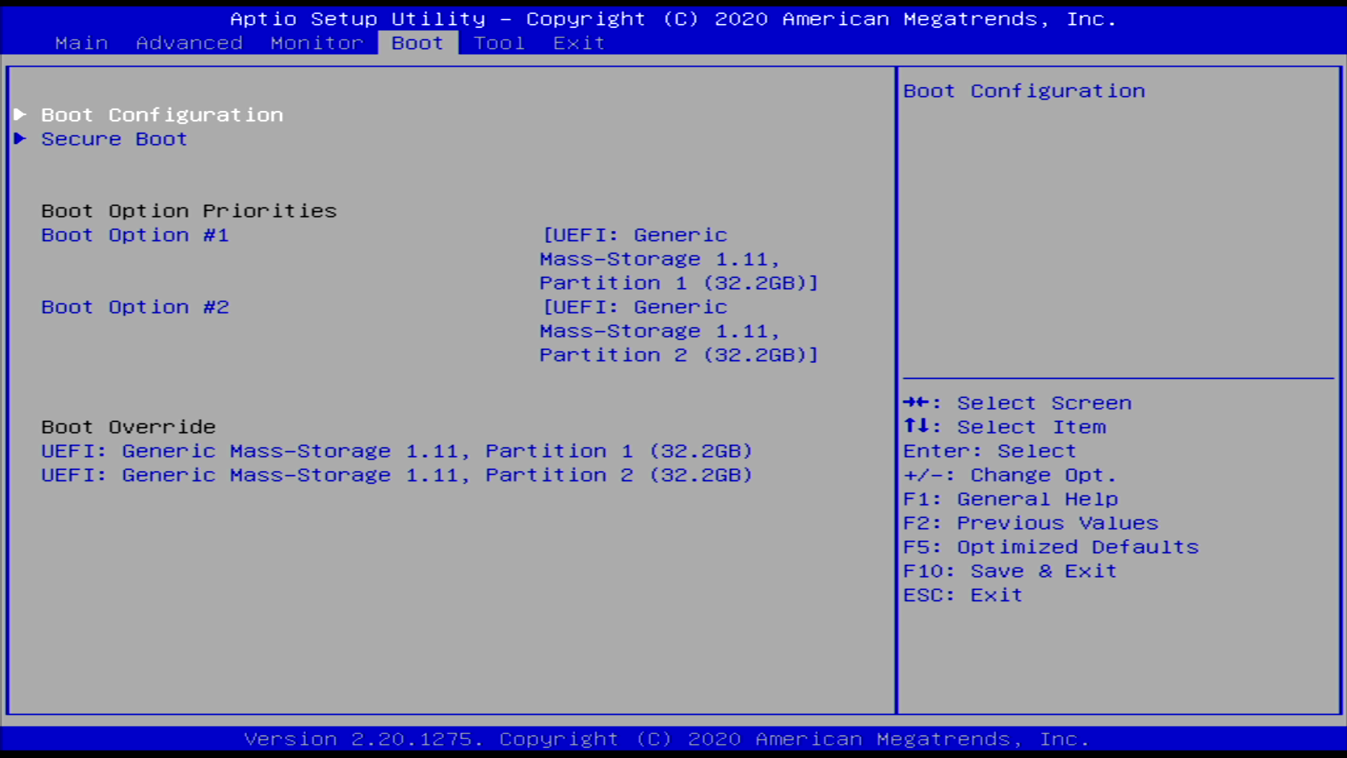
Thus far, it seems there is no option to select a temporary boot device from the main splash screen, you must first enter BIOS and then navigate to the Boot menu. It would be nice if Asus added the option to select a temporary boot device to the splash screen in a future release.

BIOS boot menu

I had no issues with 64GB of Mushkin RAM running at 3200MHz on BIOS 0409 or BIOS 0416. The PN50 ran 4 passes of Memtest86 (BIOS 0409) without any errors.

Sadly Asus offers no option to set the cTDP at 15W or 25W. From what I’ve read, the cTDP should be set to 15W in the PN50, though I am not sure how to verify this is actually the case. It would be nice if Asus offered the option to set the cTDP at 15W or 25W, though perhaps their thermal design would not accommodate that.


I have only had my PN50 for about a week, but initial impressions are quite good. It is not overly loud and performance is quite frankly amazing for the 15W TDP.

I am really excited to use the PN50 to accelerate the time consuming tasks I have now, such as buildroot make clean && make. For someone who has been using a Xeon E3-1220v3 and Xeon E5-2620v2 for compiling, the Ryzen 7 4700U is stupidly fast and sips power. It even embarrasses the Intel i9-8950HK in the XPS 15, which is a top-spec laptop from just 2 years ago.

I am excited and cannot wait to see what Cezanne brings in 2021. Hopefully Asus see fit to update their mini PC offering for future AMD platforms.

Meraki MS220: PoE support

The last several posts in this series have focused primarily on getting a custom firmware running on the Meraki MS220-series switches, without much regard for preserving existing features. Since I am now at a point where my custom firmware is functional as a Layer 2-ish switch, my attention has turned to PoE, since many switches in the series have PoE support and that is feature I think switch owners (especially MS220-8P) are interested in.

From my investigation into libpoecore included in the Meraki firmware, PoE on the MS220-8P appears to be managed by Microsemi’s PD690xx series of Power over Ethernet Management chips (datasheet). The PD690xx series communicates over I2C with the management CPU to manage PoE on the switch ports (enable/disable PoE, set 802.3af/at modes, query power consumed by a PoE device).

We can confirm that the PD690xx communicates via I2C by running poe_server from Meraki’s firmware and enabling I2C tracing in the kernel:

# cat /sys/kernel/debug/tracing/trace
# tracer: nop
#
# entries-in-buffer/entries-written: 1358/1358   #P:1
#
#                              _-----=> irqs-off
#                             / _----=> need-resched
#                            | / _---=> hardirq/softirq
#                            || / _--=> preempt-depth
#                            ||| /     delay
#           TASK-PID   CPU#  ||||    TIMESTAMP  FUNCTION
#              | |       |   ||||       |         |
      poe_server-682   [000] ....   560.356000: i2c_write: i2c-1 #0 a=030 f=0000 l=4 [13-32-0f-ff]
      poe_server-682   [000] ....   560.358000: i2c_result: i2c-1 n=1 ret=1
      poe_server-682   [000] ....   560.358000: i2c_write: i2c-1 #0 a=030 f=0000 l=2 [13-32]
      poe_server-682   [000] ....   560.358000: i2c_read: i2c-1 #1 a=030 f=0001 l=2
      poe_server-682   [000] ....   560.359000: i2c_reply: i2c-1 #1 a=030 f=0001 l=2 [0f-ff]
      poe_server-682   [000] ....   560.359000: i2c_result: i2c-1 n=2 ret=2
      poe_server-682   [000] ....   560.359000: i2c_write: i2c-1 #0 a=030 f=0000 l=4 [13-32-0f-ff]
      poe_server-682   [000] ....   560.360000: i2c_result: i2c-1 n=1 ret=1
      poe_server-682   [000] ....   560.360000: i2c_write: i2c-1 #0 a=030 f=0000 l=4 [13-9e-dc-03]
      poe_server-682   [000] ....   560.362000: i2c_result: i2c-1 n=1 ret=1

I2C tracing is extremely helpful, as running strace against poe_server directly will not yield useful output as to what operations it is performing to configure PoE.

While it is good news that we are able to recover the I2C commands via kernel tracing, it’s bad news in the sense that writing a new daemon to duplicate the features of poe_cli is non-trivial.


Thankfully, with the libpoecore from the Meraki firmware dump and free disassembly tools like Ghidra (sorry Hex-Rays, support MIPS in IDA Free ¯\_(ツ)_/¯), understanding some of the logic behind functionality provided by poe_server and poe_cli becomes much easier.

If you disassemble libpoecore, you can find the function hard_init which contains code to set up GPIO outputs. Interesting to note is that while the GPIO pins change depending on which switch ASIC is present, the sequence of GPIO outputs to configure the PD690xx remains constant.

Disassembler view of the function hard_init from the library libpoecore.so

The same GPIO configuration is executed when switch_brain is started (full strace output):

writev(1, [{iov_base="", iov_len=0}, {iov_base="echo 7 > /sys/class/gpio/export\n", iov_len=32}], 2echo 7 > /sys/class/gpio/export) = 32
writev(1, [{iov_base="", iov_len=0}, {iov_base="echo 12 > /sys/class/gpio/export\n", iov_len=33}], 2echo 12 > /sys/class/gpio/export) = 33
writev(1, [{iov_base="", iov_len=0}, {iov_base="echo out > /sys/class/gpio/gpio7/direction\n", iov_len=43}], 2echo out > /sys/class/gpio/gpio7/direction) = 43
writev(1, [{iov_base="", iov_len=0}, {iov_base="echo out > /sys/class/gpio/gpio12/direction\n", iov_len=44}], 2echo out > /sys/class/gpio/gpio12/direction) = 44
writev(1, [{iov_base="", iov_len=0}, {iov_base="echo 1 > /sys/class/gpio/gpio7/value\n", iov_len=37}], 2echo 1 > /sys/class/gpio/gpio7/value) = 37
writev(1, [{iov_base="", iov_len=0}, {iov_base="echo 0 > /sys/class/gpio/gpio12/value\n", iov_len=38}], 2echo 0 > /sys/class/gpio/gpio12/value) = 38
writev(1, [{iov_base="", iov_len=0}, {iov_base="echo 1 > /sys/class/gpio/gpio12/value\n", iov_len=38}], 2echo 1 > /sys/class/gpio/gpio12/value) = 38
writev(1, [{iov_base="", iov_len=0}, {iov_base="echo 0 > /sys/class/gpio/gpio7/value\n", iov_len=37}], 2echo 0 > /sys/class/gpio/gpio7/value) = 37
writev(1, [{iov_base="", iov_len=0}, {iov_base="echo 1 > /sys/class/gpio/gpio12/value\n", iov_len=38}], 2echo 1 > /sys/class/gpio/gpio12/value) = 38

The datasheet for the luton26 ASIC used in the MS220-8P, MS220-24P, and MS22 (VDMS-10393) doesn’t list anything connected to GPIO 7, and GPIO 12 is used for either SFP17_SD or PHY7_LED1 depending on the overlay function chosen. The functionality of these GPIO pins is undefined in the ASIC datasheet, however libpoecore is setting them and manipulating their outputs.

We can implement the logic of hard_init in an init script to set up the GPIO pins in the same way, and the result is that the PD690xx is configured for auto mode. I am not sure how, there is nothing in the PD690xx datasheet which suggests GPIO pins can be used to configure the operating mode, but the switch will automatically negotiate and power a PoE device.

Writing a new daemon to communicate with the PD690xx will ultimately be necessary if fine control over PoE functionality is to be achieved. Without I2C communication to the PD690xx, it is not possible to query the power budget, or limit port power delivery. In the mean time, for those who do not mind unmanaged “plug-and-play” style, PoE can be considered functional.

MS220-8P: Custom firmware from scratch

To follow up on my previous posts about modifying the firmware for the Cisco Meraki MS220-8P, I have more progress to report.

Since I could not figure out how to fix serial output from userspace when booting from u-boot, I went back to booting with RedBoot and tried to focus on improving userspace from my first sloppy attempt to coerce the Meraki firmware into booting from NOR.

Here is the current situation:

  • RedBoot without CRC or kernel size checks
  • Kernel 3.18.123 with xz compression
  • Busybox userspace based on buildroot 2020.02.1
  • Meraki kernel modules: vtss_core, proclikefs, merakiclick, elts_meraki, and vc_click are successfully loaded during boot
  • The click router is successfully initialized, creating the interfaces arping, linux_mgmt, sw0_pcap, and wired0

However, networking is non-functional. The switch broadcasts DHCP requests, but no packets are ever passed from the switching ASIC to the management CPU:

arping    Link encap:Ethernet  HWaddr 88:15:44:73:22:31
          inet addr:169.254.55.143  Bcast:169.254.255.255  Mask:255.255.0.0
          inet6 addr: fe80::8a15:44ff:fe73:2231/64 Scope:Link
          UP BROADCAST RUNNING MULTICAST  MTU:1500  Metric:1
          RX packets:0 errors:0 dropped:0 overruns:0 frame:0
          TX packets:33 errors:0 dropped:0 overruns:0 carrier:0
          collisions:0 txqueuelen:0
          RX bytes:0 (0.0 B)  TX bytes:5546 (5.4 KiB)

linux_mgmt Link encap:UNSPEC  HWaddr 00-00-00-00-00-00-00-00-00-00-00-00-00-00-00-00
          UP POINTOPOINT RUNNING NOARP MULTICAST  MTU:1500  Metric:1
          RX packets:0 errors:0 dropped:0 overruns:0 frame:0
          TX packets:0 errors:0 dropped:0 overruns:0 carrier:0
          collisions:0 txqueuelen:0
          RX bytes:0 (0.0 B)  TX bytes:0 (0.0 B)

lo        Link encap:Local Loopback
          inet addr:127.0.0.1  Mask:255.255.255.255
          inet6 addr: ::1/128 Scope:Host
          UP LOOPBACK RUNNING  MTU:65536  Metric:1
          RX packets:0 errors:0 dropped:0 overruns:0 frame:0
          TX packets:0 errors:0 dropped:0 overruns:0 carrier:0
          collisions:0 txqueuelen:0
          RX bytes:0 (0.0 B)  TX bytes:0 (0.0 B)

sw0_pcap  Link encap:Ethernet  HWaddr 00:01:02:03:04:05
          inet addr:169.254.83.119  Bcast:169.254.255.255  Mask:255.255.0.0
          inet6 addr: fe80::201:2ff:fe03:405/64 Scope:Link
          UP BROADCAST RUNNING MULTICAST  MTU:1500  Metric:1
          RX packets:0 errors:0 dropped:0 overruns:0 frame:0
          TX packets:32 errors:0 dropped:0 overruns:0 carrier:0
          collisions:0 txqueuelen:0
          RX bytes:0 (0.0 B)  TX bytes:5476 (5.3 KiB)

wired0    Link encap:UNSPEC  HWaddr 00-00-00-00-00-00-00-00-00-00-00-00-00-00-00-00
          UP POINTOPOINT RUNNING NOARP MULTICAST  MTU:1500  Metric:1
          RX packets:0 errors:0 dropped:0 overruns:0 frame:0
          TX packets:0 errors:0 dropped:0 overruns:0 carrier:0
          collisions:0 txqueuelen:0
          RX bytes:0 (0.0 B)  TX bytes:0 (0.0 B)

On the other side:

tcpdump: listening on eth1, link-type EN10MB (Ethernet), capture size 262144 bytes
06:02:32.423798 IP6 (hlim 1, next-header Options (0) payload length: 36) fe80::201:c0ff:fe1f:9fb2 > ff02::16: HBH (rtalert: 0x0000) (padn) [icmp6 sum ok] ICMP6, multicast listener report v2, 1 group record(s) [gaddr ff02::1:ff1f:9fb2 to_ex { }]
06:02:33.097129 IP6 (hlim 1, next-header Options (0) payload length: 36) fe80::201:c0ff:fe1f:9fb2 > ff02::16: HBH (rtalert: 0x0000) (padn) [icmp6 sum ok] ICMP6, multicast listener report v2, 1 group record(s) [gaddr ff02::1:ff1f:9fb2 to_ex { }]
06:03:20.969517 IP (tos 0x0, ttl 64, id 20247, offset 0, flags [none], proto UDP (17), length 332, bad cksum 2a8b (->1677)!)
    0.0.10.10.68 > 10.10.255.255.67: [bad udp cksum 0x17ca -> 0x03b6!] BOOTP/DHCP, Request from 88:15:44:21:65:10 (oui Unknown), length 304, xid 0xd3650d76, secs 123, Flags [none] (0x0000)
          Client-Ethernet-Address 88:15:44:21:65:10 (oui Unknown)
          Vendor-rfc1048 Extensions
            Magic Cookie 0x63825363
            DHCP-Message Option 53, length 1: Discover
            Client-ID Option 61, length 15: hardware-type 255, 44:21:65:10:00:03:00:01:88:15:44:21:65:10
            SLP-NA Option 80, length 0""
            NOAUTO Option 116, length 1: Y
            MSZ Option 57, length 2: 1472
            Hostname Option 12, length 13: "m881544216510"
            T145 Option 145, length 1: 1
            Parameter-Request Option 55, length 14:
              Subnet-Mask, Classless-Static-Route, Static-Route, Default-Gateway
              Domain-Name-Server, Hostname, Domain-Name, MTU
              BR, Lease-Time, Server-ID, RN
              RB, Option 119
            END Option 255, length 0
06:04:25.620540 IP (tos 0x0, ttl 64, id 13784, offset 0, flags [none], proto UDP (17), length 332, bad cksum 43ca (->2fb6)!)
    0.0.10.10.68 > 10.10.255.255.67: [bad udp cksum 0x178a -> 0x0376!] BOOTP/DHCP, Request from 88:15:44:21:65:10 (oui Unknown), length 304, xid 0xd3650d76, secs 187, Flags [none] (0x0000)
          Client-Ethernet-Address 88:15:44:21:65:10 (oui Unknown)
          Vendor-rfc1048 Extensions
            Magic Cookie 0x63825363
            DHCP-Message Option 53, length 1: Discover
            Client-ID Option 61, length 15: hardware-type 255, 44:21:65:10:00:03:00:01:88:15:44:21:65:10
            SLP-NA Option 80, length 0""
            NOAUTO Option 116, length 1: Y
            MSZ Option 57, length 2: 1472
            Hostname Option 12, length 13: "m881544216510"
            T145 Option 145, length 1: 1
            Parameter-Request Option 55, length 14:
              Subnet-Mask, Classless-Static-Route, Static-Route, Default-Gateway
              Domain-Name-Server, Hostname, Domain-Name, MTU
              BR, Lease-Time, Server-ID, RN
              RB, Option 119
            END Option 255, length 0

The primary reason for this appears to be because Meraki is using the click modular router. Click seems to be an attempt to lobotomize the Linux kernel networking stack for the sake of writing academic research papers. The kernel side of click was never upstreamed to mainline and is no longer maintained. Let us pour one out for the poor soul at Cisco who has to maintain this.

Since Meraki was spun out of MIT and the researchers who wrote Click were also at MIT, the relationship between Meraki and Click is clear. Finally Click found a practical use, in a now-obsolete product line from Cisco.

More reverse engineering is necessary to make Click functional enough to have basic connectivity to the management CPU.


The strace output of switch_brain is available in this gist. By first running switch_brain, and then overwriting the default traffic rules with “allow all” I was able to SSH to the management CPU:

/ # echo "allow all" > /click/nat/common_switch_nat/from_smc_filter/config
/ # echo "allow all" > /click/nat/common_switch_nat/from_mgmt_filter/config
/ # tail /tmp/messages | grep dropbear
Jan  1 00:15:49 buildroot authpriv.info dropbear[680]: Child connection from 10.10.10.1:39248
Jan  1 00:15:50 buildroot authpriv.notice dropbear[680]: Password auth succeeded for 'root' from 10.10.10.1:39248
/ # w
USER            TTY             IDLE    TIME             HOST
root            pts/0           00:00   Jan  1 00:15:50  10.10.10.1

I think it is now very clear that the “only” thing blocking full access to the management CPU is the Click configuration. My hope is to build the configuration from the switch_brain strace output and package that into an initscript.

I have updated the meraki-builder repository with the buildroot config file and overlay directory I use to inject init scripts (among other things).

If you would like to contribute, I have written some installation instructions for the current development firmware. If you find the correct voodoo of Click commands to access the management CPU, please open a PR 🥰 The voodoo has been found.