Fujitsu TX140 S2

The SuperMicro X10SLE-F is nice, but it has very limited expansion; no PCIe slots and the MicroLP adapters with SFP+ are insanely expensive. Fujitsu motherboards, in the EU, are quite cheap (33€ on eBay) and I have never owned a Fujitsu system before, so I thought I would give it a try.

Fujitsu TX140 S2 motherboard

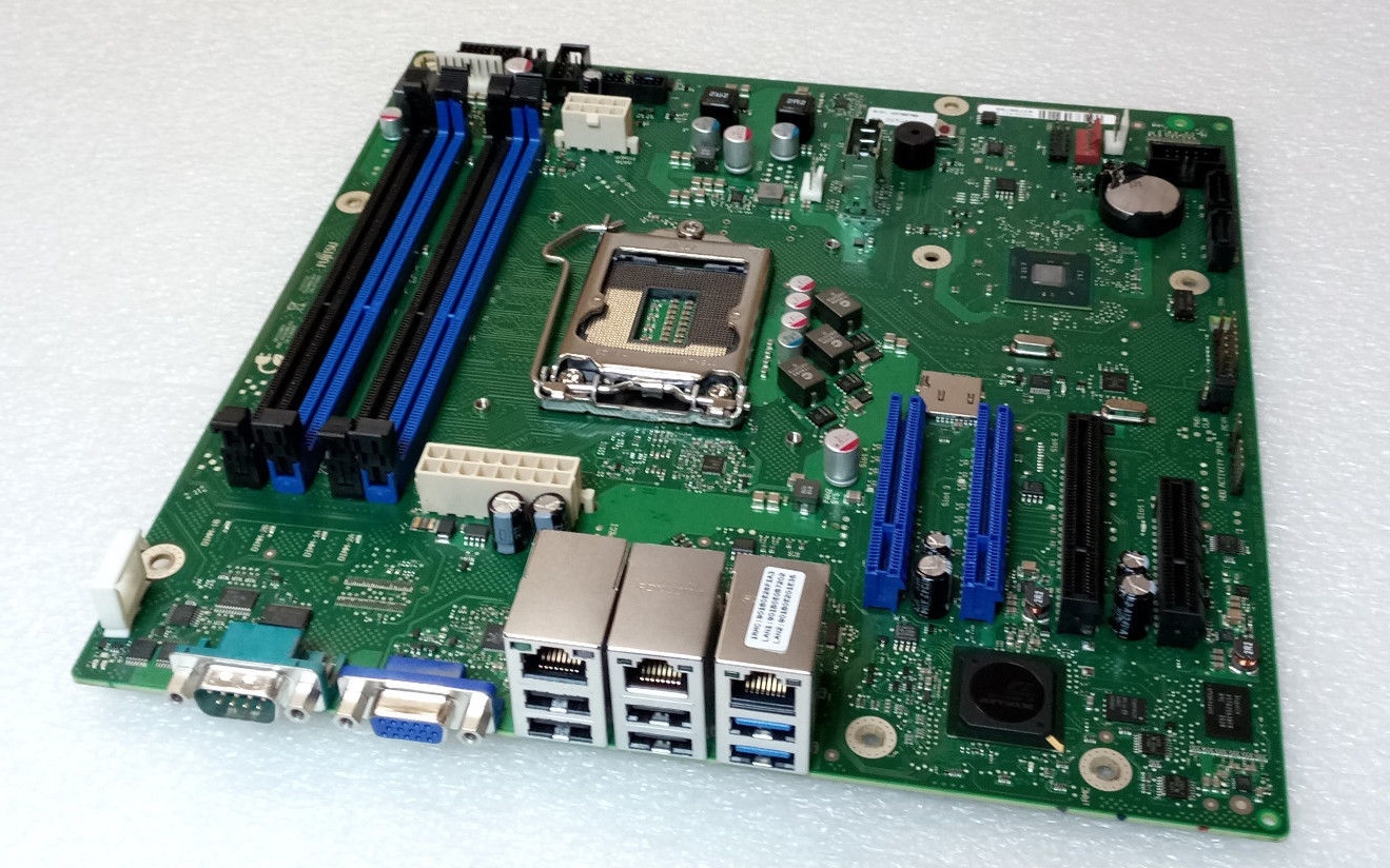
The first order of business, since I bought a bare motherboard, is to power it from an ATX power supply. Luckily for me, other people have determined the 16-pin power supply pinout:

Fujitsu 16-pin power supply pinout

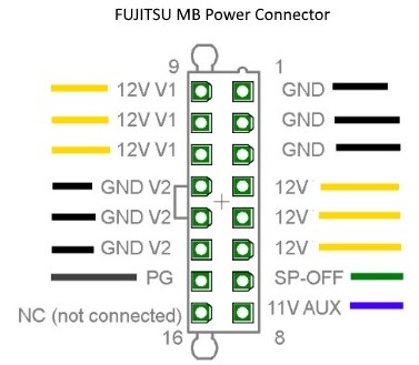
Side note: this appears to be a common power supply connector for Fujitsu motherboards with a 16-pin power connector. The Celsius W520 uses the same pinout.

The 12V rail appears to go directly to the PCIe slots and is completely isolated from 12V V1.


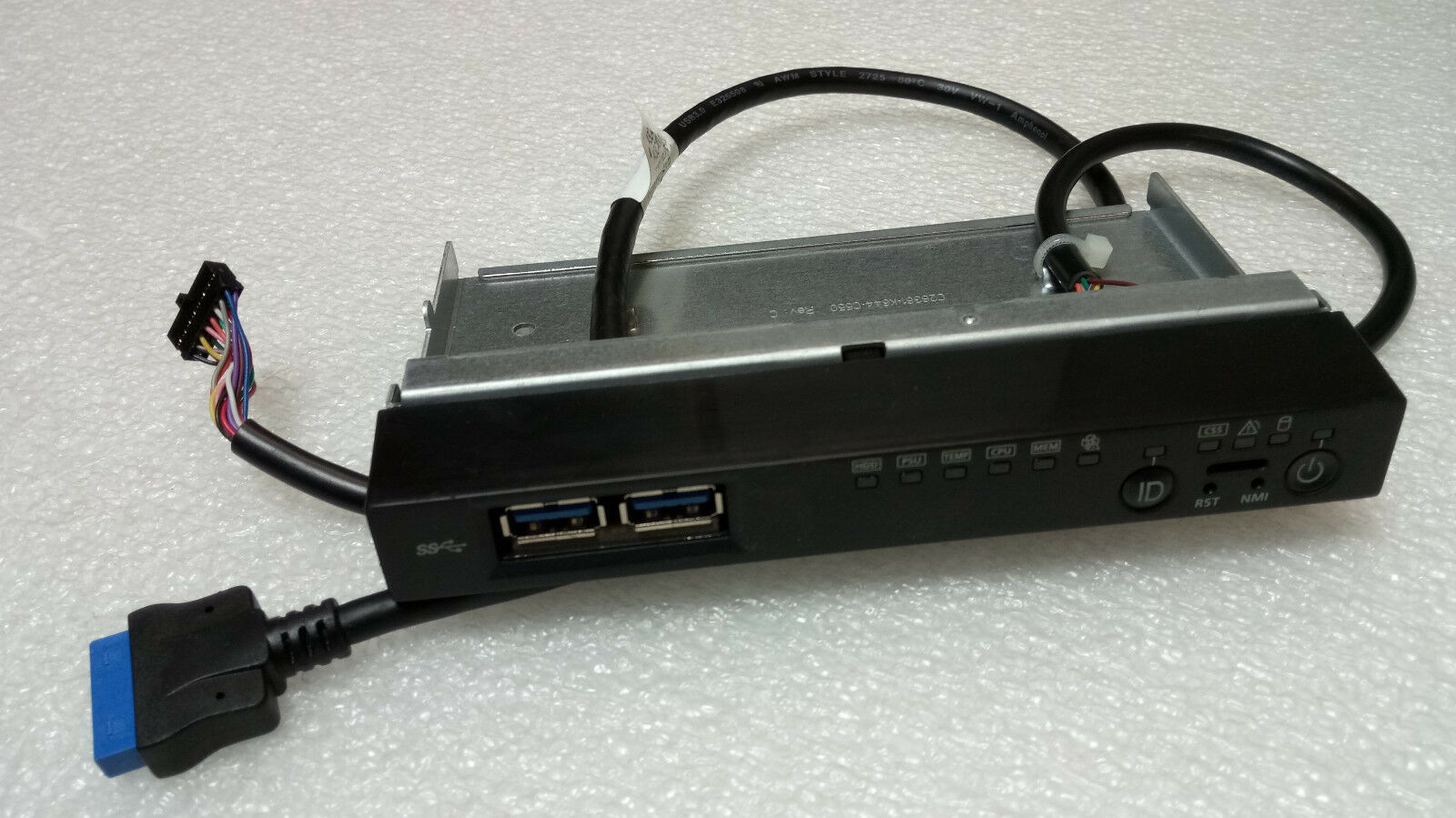
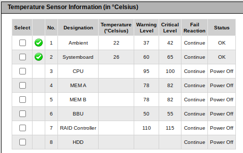
If the ambient temperature sensor is absent, iRMC considers the system in an error state. The Global Error/CSS lights are flashing and the fans run at full speed (100% PWM).

Unfortunately the ambient temperature sensor is integrated into the front-panel assembly (c26361-k644-c550), which I don’t have:

I couldn’t locate the technical manual for the TX140 S2 (D3239), but technical manual of the TX140 S1 (D3049) has the following to say:

Measurement of the processor and the system internal temperature by an onboard temperature sensor, measurement of the ambient temperature by a I²C temperature sensor.

System board D3049 for PRIMERGY TX140 S1 / TX120 S3 – Technical Manual

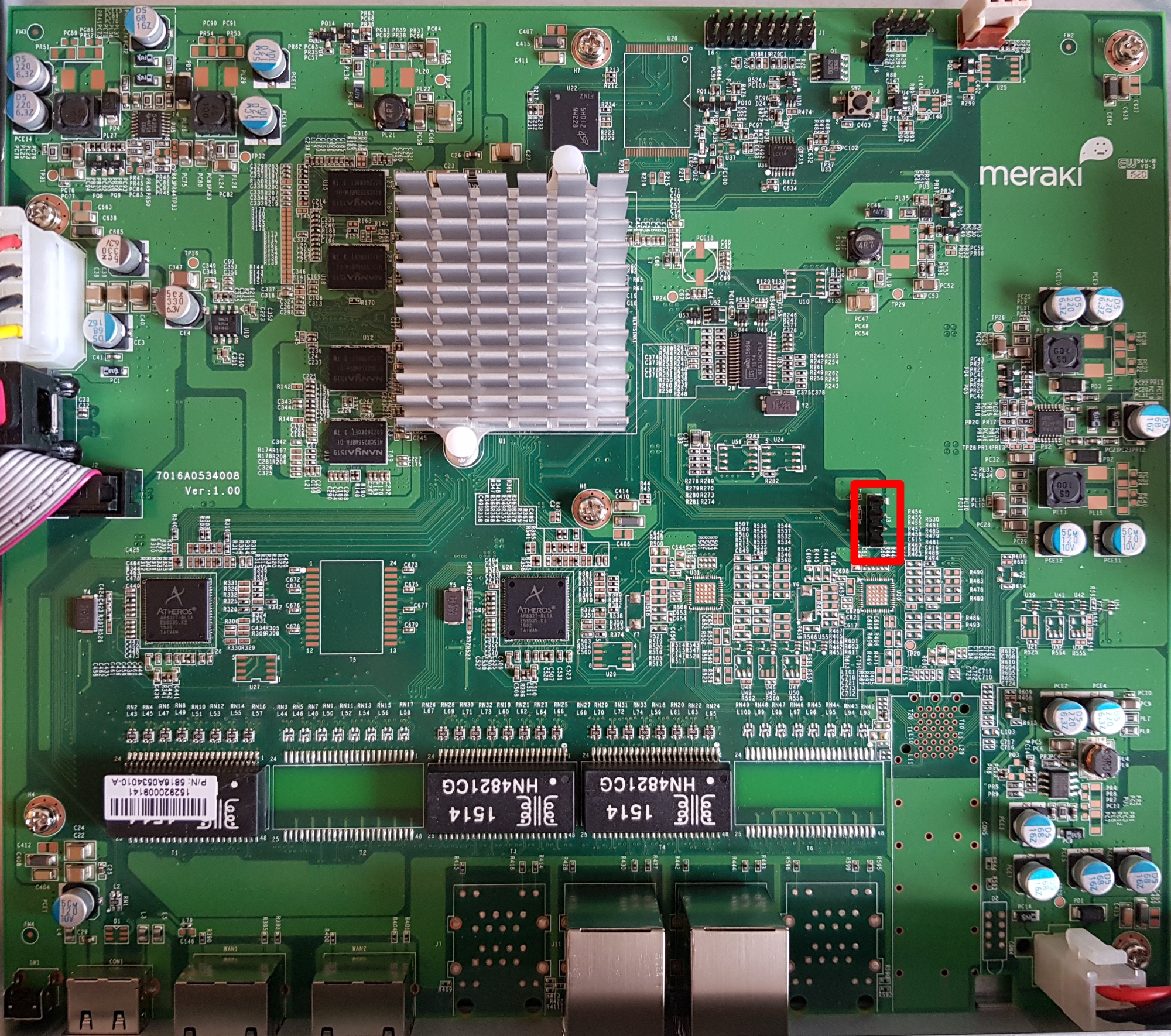
I am unaware of any publicly available pinout of the 16 pin front-panel header (2×8, 2.0mm spacing), so I reverse engineered it:
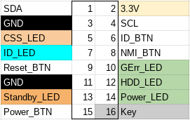
Fujitsu TX140 S2 front panel pinout

In table format:

PinDescriptionPinDescription
1SDA (serial data)23.3V
3Ground4SCL (serial clock)
5CSS LED positive (Customer self service)6ID button
7ID LED+ (anode)8NMI button
9Reset button10Global Error LED+ (anode)
11Ground12HDD activity LED+ (anode)
13Standby LED+ (anode)14Power LED+ (anode)
15Power button16Key (pin absent)
Fujitsu TX140 S2 front panel pinout

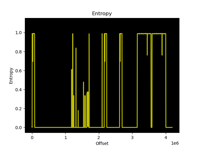
We can confirm the I²C pins with a logic analyzer:

I²C found

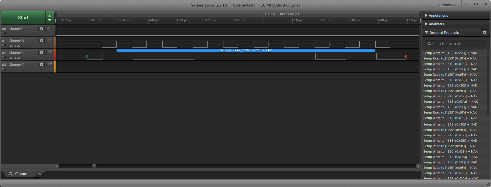
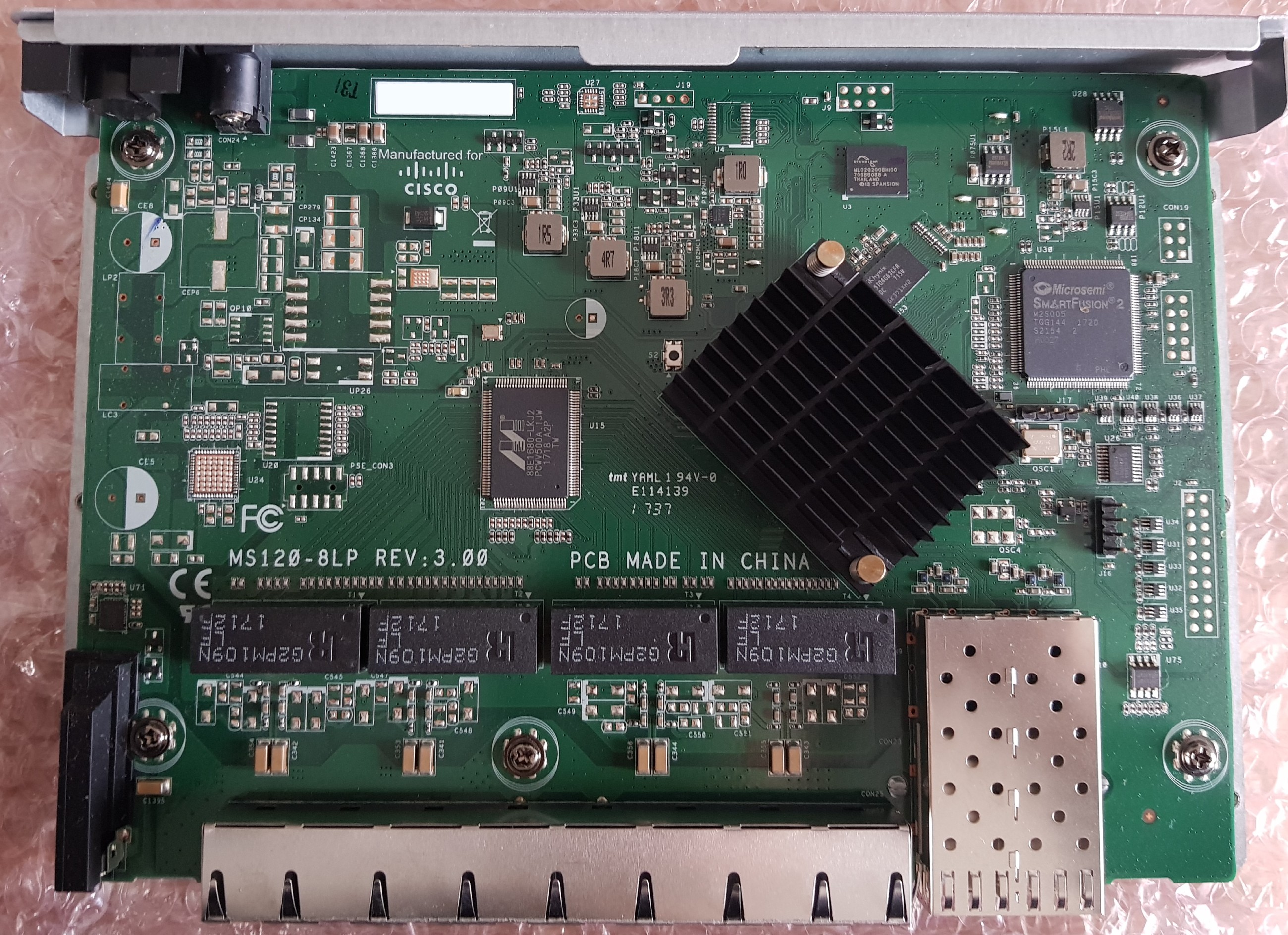
Now unfortunately, there are no high resolution photos of the front-panel PCB, so it’s not possible to easily determine which I²C temperature sensor is being used.

There is a photo of a Fujitsu RX300 front-panel with a failed temperature sensor, but that is only enough to allow us to guess the chip model as the Texas Instruments LM75.

The CJMCU-75 is a cheap and readily available LM75 sensor

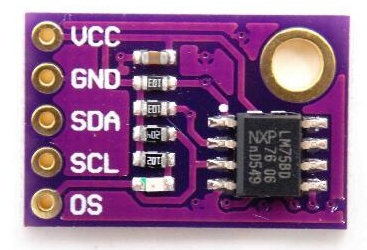
We can also guess the I²C address from the RX300 front-panel: all 3 address lines should be tied to VCC.

Now with the sensor connected to the front-panel connector using the pinout above, it is time to find out if Fujitsu used the same ambient temperature sensor on the RX300 and TX140 S2, and if I guessed the I2C address correctly.

Yes, iRMC S4 reads the ambient temperature from the CJMCU LM75!

There is a chassis IDPROM also in the front panel assembly, which from the iRMC log appears to store a backup of the BIOS parameters after successful POST. I consider the IDPROM somewhat optional, as iRMC does not consider it a critical component in terms of server functionality.


First impressions are good, power consumption is very low, though not as low as the X10SLE-F. Idle power consumption in Linux is under 20W with an E3-1220 v3 and 16GB of PC3L-12800E.

lspci output:

00:00.0 Host bridge: Intel Corporation Xeon E3-1200 v3 Processor DRAM Controller (rev 06)
00:01.0 PCI bridge: Intel Corporation Xeon E3-1200 v3/4th Gen Core Processor PCI Express x16 Controller (rev 06)
00:01.1 PCI bridge: Intel Corporation Xeon E3-1200 v3/4th Gen Core Processor PCI Express x8 Controller (rev 06)
00:14.0 USB controller: Intel Corporation 8 Series/C220 Series Chipset Family USB xHCI (rev 05)
00:19.0 Ethernet controller: Intel Corporation Ethernet Connection I217-LM (rev 05)
00:1a.0 USB controller: Intel Corporation 8 Series/C220 Series Chipset Family USB EHCI #2 (rev 05)
00:1c.0 PCI bridge: Intel Corporation 8 Series/C220 Series Chipset Family PCI Express Root Port #1 (rev d5)
00:1c.2 PCI bridge: Intel Corporation 8 Series/C220 Series Chipset Family PCI Express Root Port #3 (rev d5)
00:1d.0 USB controller: Intel Corporation 8 Series/C220 Series Chipset Family USB EHCI #1 (rev 05)
00:1f.0 ISA bridge: Intel Corporation C224 Series Chipset Family Server Standard SKU LPC Controller (rev 05)
00:1f.2 SATA controller: Intel Corporation 8 Series/C220 Series Chipset Family 6-port SATA Controller 1 [AHCI mode] (rev 05)
00:1f.3 SMBus: Intel Corporation 8 Series/C220 Series Chipset Family SMBus Controller (rev 05)
00:1f.6 Signal processing controller: Intel Corporation 8 Series Chipset Family Thermal Management Controller (rev 05)
03:00.0 VGA compatible controller: Matrox Electronics Systems Ltd. MGA G200e [Pilot] ServerEngines (SEP1) (rev 05)
03:00.1 Co-processor: Emulex Corporation ServerView iRMC HTI
04:00.0 Ethernet controller: Intel Corporation I210 Gigabit Network Connection (rev 03)

I have requested the GPL source code of iRMC from Fujitsu, and if they get back to me with the source code I may have some interesting findings to share. Stay tuned…

Meraki MX80: buildroot firmware

Ten years ago, before ARM was in everything, many embedded systems that did not justify using an x86 used PowerPC (or MIPS). This leads us to today’s subject: the Meraki MX80, an “enterprise security appliance.”

Meraki MX80 marketing image

Meraki MX80

The MX80 is End-of-Life (EOL) and can be purchased quite inexpensively on eBay.

The MX-series differs from other Meraki networking products of the 2010-era that we have previously covered (the MS220) in that it is PowerPC based (APM86290) with 2GB of RAM and 1GB of NAND flash. The factory bootlog of the device can be found in this GitHub gist.


MX80 PCB with uart header highlighted

MX80 UART header

Removing the cover allows you to connect to the UART header J3 (57600n8), with the pinout:

  1. VCC (don’t connect)
  2. Rx
  3. Tx
  4. GND

Ground (pin 4) is closest to the Ethernet ports.

Obtaining a root shell is very easy as u-boot has a 1 second boot delay and accepts input on UART. The default meraki_boot target sets the bootargs from meraki_bootargs which appends extra_bootargs, so just override rdinit with /bin/sh to prevent the Meraki OS from booting.

setenv extra_bootargs rdinit=/bin/sh
run meraki_boot

Once the MX80 has booted, bring up eth0 (port label Internet on the MX80):

$ mount -t proc proc /proc
$ mount -t sysfs sysfs /sys
$ ifconfig lo up
$ ifconfig eth0 up
$ udhcpc eth0

Once you have functional networking, you can dump the contents of NAND to a remote host for further analysis:

$ cat /proc/mtd
dev:    size   erasesize  name
mtd0: 00100000 00020000 "firmware"
mtd1: 00100000 00020000 "environment"
mtd2: 00040000 00020000 "oops-old"
mtd3: 3fdc0000 00020000 "ubi"
mtd4: 40000000 00020000 "all"
mtd5: 0201d800 0001f800 "part1"
mtd6: 0201d800 0001f800 "part2"
mtd7: 0001f800 0001f800 "board-config"
mtd8: 2001f000 0001f800 "storage"
$ dd if=/dev/mtdblock4 bs=1M | gzip -c | nc -l -p 5000

Running binwalk on “part1” shows us the structure of Meraki’s firmware:

$ binwalk part1.bin

DECIMAL       HEXADECIMAL     DESCRIPTION
--------------------------------------------------------------------------------
1024          0x400           device tree image (dtb)
16384         0x4000          device tree image (dtb)
131072        0x20000         uImage header, header size: 64 bytes, header CRC: 0xD84034B5, created: 2020-05-29 01:15:36, image size: 2447726 bytes, Data Address: 0x0, Entry Point: 0x0, data CRC: 0xCE3A4A5E, OS: Linux, CPU: PowerPC, image type: OS Kernel Image, compression type: gzip, image name: "Linux-3.4.113"
131136        0x20040         gzip compressed data, maximum compression, from Unix, last modified: 1970-01-01 00:00:00 (null date)
4194304       0x400000        uImage header, header size: 64 bytes, header CRC: 0xDA83B155, created: 2020-05-29 01:16:17, image size: 16719915 bytes, Data Address: 0x0, Entry Point: 0x0, data CRC: 0x2381914F, OS: Linux, CPU: PowerPC, image type: RAMDisk Image, compression type: lzma, image name: "Simple Ramdisk Image"
4194368       0x400040        LZMA compressed data, properties: 0x5D, dictionary size: 67108864 bytes, uncompressed size: -1 bytes

There is a device tree image at offset 0x400 which seems to be for the MX60 (codename bluestone). There is a second device tree image at offset 0x4000 for the MX80 (codename fullerene).

It is not as simple as creating a binary image with the DTB at offset 0x4000, the kernel at 0x200000, and initrd at 0x40000 because Meraki have modified u-boot to have a custom command meraki which reads a header, verifies the contents of the ubi partition part1 or part2 with SHA1, and then sets environment variables from addresses defined in the header.

The layout of the header is as follows:

Header field Data type (value)
SHA1_MAGIC uint32 (0x8e73ed8a)
HEADER_LEN int32
DATA_LEN int32
SHA1SUM char[20]
MERAKI_EXTRA_MAGIC uint32 (0xa1f0beef)
MERAKI_EXTRA_LEN uint16 (0x0006)
MERAKI_EXTRA_TYPE uint16 (0x0001)
IMAGE_OFFSET uint32 (0x20000)
RAMDISK_OFFSET uint32 (0x400000)
FDT_OFFSETS array uint32 (0x400 or 0x4000)

The FDT used to boot depends on the value of meraki_part_fdt_index in u-boot. For the MX80, the index of the FDT offset is 1, meaning the FDT located at 0x4000 is used to boot. The presence of two FDTs suggests that Meraki are using the same firmware for both the MX60 and MX80. Despite the MX80 being a dual core CPU only one CPU core is usable, there is no SMP support in the kernel provided by Meraki.


To simplify booting, I have written a post-image.sh script which generates the appropriate header and assembles a bootable firmware image as part of the buildroot build process. You can find instructions on how to build the firmware in the meraki-builder GitHub repository.

The 3.4 kernel provided by Meraki doesn’t have any of the features required by OpenWrt (e.g. overlayfs) and buildroot doesn’t have a package manager. If you just want something to boot and run SSH on, then the buildroot image fulfills that need. You will most probably want to customize buildroot to include the packages and configuration that suits your needs. Upstream support in OpenWrt is still a long way away, as the APM86290 does not have support in the mainline kernel.

Meraki MS120 hardware overview

I received an innocent sounding question via GitHub, would the custom firmware I have been developing for the MS220 work on an MS120?

I am an eternal sucker for good mysteries involving hardware, so I found a seller on eBay offering an MS120-8-HW for $95 USD (plus shipping and customs to the EU). A few weeks of buyer’s remorse and waiting, and I had the MS120 in my hands.

One thing that immediately struck me about the MS120 is the material change from aluminum to steel. While I thought Meraki’s use of anodized aluminum in the MS220 series was a silly choice for the larger rack mounted models, it did make me think they were attempting to position themselves as the Apple Computer of networking products (“You pay the premium because we’re different”). Regardless of their intentions with the aluminum MS220 series, it was a precedent and it cheapens the experience to see them swap out aluminum for steel.

Let us continue, because whinging about metal choices is not bringing us closer to answering the original question.

MS120 PCB

Inside the MS120-8-HW

The MS120 is based on the Marvell Alleycat3 platform, referred to as kelpie-8 in the u-boot source and otherwise known by its marketing name “Prestera.” It is an ARMv7 core running at 400MHz with 512MB of DDR3 and 256MB of NAND flash.

The UART header is J16 at 115200n8 with the pinout:

  1. Vcc (Do not connect)
  2. Rx
  3. Tx
  4. GND

Pin 1 is closest to the SFP cage.

J17 is a mystery jumper. I have not identified its purpose yet.


There is 32Mbit (4MB) of SPI flash present, however as far as I can tell, this is connected directly to the Microsemi SmartFusion 2 and not to the Marvell ASIC. Using a hardware reader and a chip clip, I dumped the contents to examine it. Running binwalk yielded no results.

The entropy graph of the dump suggests that there are multiple copies of the same data stored, which follows Meraki’s design with the MS220 switches where there are primary and backup copies of the bootloader.

Entropy of the 32Mbit flash of the M120

Entropy graph of the 32Mbit flash in the MS120

Further inspection confirms that there are two identical copies of what I think is u-boot stored in the flash, starting at 0x301000. Each copy is approximately 420KB, which would correspond to the size of u-boot for this platform. However, the entropy is much higher than the entropy of u-boot.bin built using the Meraki GPL source, and contains only one readable string: kelpie_top

Perhaps this is the output of u-boot after running doimage to enable Secure Boot and AES-128 encryption?

The PCB traces from the winbond flash appear to go directly to the SmartFusion 2, but the u-boot UART output shows that the BootROM is booting from SPI:

BootROM 1.41
Booting from SPI flash

Is the SmartFusion 2 emulating an SPI device to the Alleycat3 after verifying the integrity of the u-boot binary in ROM?

u-boot then executes an application at memory address 0x0C100000 that prints the value of multiple “SecureBoot Registers” the strings of which do not appear anywhere in the u-boot code provided in the GPL archive:

## Starting application at 0x0C100000 ...

----Security Versions----
SecureBoot: R03.11b39af022017-07-25
SB Core: F01114R18.1680555472017-07-12
Microloader: MG0008R01.0103302017

----SecureBoot Registers----
system_invalid: 0
boot_check_count_error: 0
boot_done: 1
boot_ok: 1
boot_check_count_golden: 0
boot_check_count_upgrade: 2
boot_status_golden: 0
boot_status_upgrade: 1
first_bootloader: 1

----Upgrade----
boot_error: 0
boot_check_count_error_vc: 0
boot_check_count_error: 0
boot_timeout_vc: 0
boot_timeout: 0
boot_cs_good: 1
boot_config_error: 0
boot_version_error: 0
boot_config_error_code: 0
boot_error_code: 0
boot_cs_good: 1
boot_version_error: 0
boot1_cs_key_type: 1
boot1_cs_return_code: 0
boot1_cs_key_index: 5
boot2_cs_return_code: 0
boot2_cs_key_index: 5
boot2_cs_key_type: 1

----Other Registers----
fpga_version: 001b

Meraki do not include the build toolchain in their GPL archive. Luckily, I remembered that I have encountered this Marvell fork of u-boot before, for the Western Digital EX2100 which also uses a Marvell Armada 385 from the same family of ARMv7 CPU cores. Western Digital does include the Marvell toolchain used to compile u-boot in their GPL archive, good guy Western Digital!

To save anyone else the effort of setting up a development environment with an ancient version of GCC, I have created a Dockerfile that will handle building u-boot using the Marvell toolchain. You can find this work on GitHub.


I reached out to members of the Doozan forum who have been building Linux images for Marvell based NAS devices for many years to see if they had any more information about Secure Boot. Apparently Marvell CPUs will always kwboot before loading from other sources such as SPI or NAND:

Even if a box has secure boot in stock FW (u-boot, kernel,..), you should be able to kwboot it with a non-secure u-boot/spl binary.

I tried to kwboot the MS120 (with and without the Armada patches), but was unable to get it working. For some reason, the BootROM output is printed twice when kwboot is running, which I have not witnessed during any normal boot sequence:

$ ./kwboot -b u-boot.uart -f -t -B 115200 /dev/ttyUSB0
Sending boot message. Please reboot the target.../
BootROM 1.41
Pattern detected on UART-
BootROM 1.41
Pattern detected on UART/

uart.bin was created using tools/marvell/doimage:

$ ./doimage -T uart -D 0x0 -E 0x0 u-boot.bin u-boot.uart

Unfortunately, this investigation leaves us with more questions than answers.

  • What is the contents of the 32Mbit SPI flash?
    • Does the SmartFusion 2 only provide glue logic, or does it also protect/verify the contents of SPI flash?
  • Why won’t the Alleycat3 kwboot?
    • Is the duplicate output from BootROM when kwboot is invoked a clue?
  • What is the purpose of the header J17?
  • Why did Meraki switch from aluminum to steel?

The MS120 series is a completely different platform from the previous MS220 series, which used Vitesse ASICs with a MIPS core, 128MB of DDR2, 16MB of SPI, and 128MB of NAND flash.

The use of Secure Boot will complicate efforts to create a third-party firmware for the MS120 series. However, the more immediate issue is that kwboot does not work and there is no obvious copy of u-boot in SPI flash we can modify to alter the boot process.