Tag Archives: intel

HP ThunderBolt 120W G4 Dock teardown

I bought an HP ThunderBolt 120W G4 dock (4J0A2AA) because the Dell TB16 I have been using for years does not work well with the Framework Laptop 13″ (13th Gen; i5-1340P).

The Dell TB16 is recognized by the Framework Laptop and does function, however only the mini-DisplayPort output works. Despite repeated attempts, I could not make multiple monitor outputs function with the Framework Laptop and the TB16, which is annoying as I had two displays (DisplayPort and mini-DisplayPort) running at 4K60 from the XPS 9570.

HP ThunderBolt 120W G4 dock, HP product image

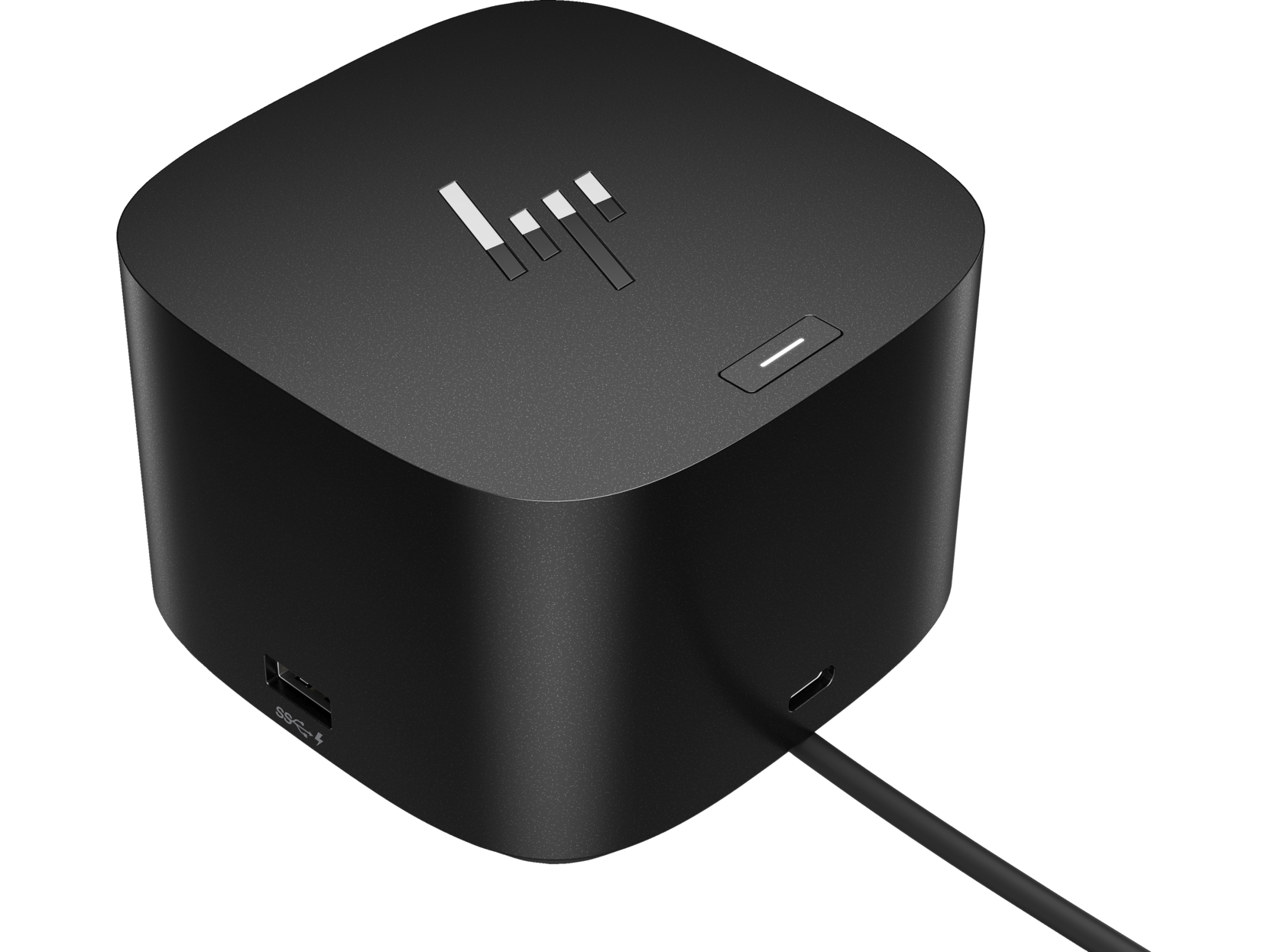
The HP Thunderbolt G4 dock is quite new and supports USB4 on the upstream port to the host (the dock ports support USB 3.2 Gen 2). Multiple displays work with the Framework Laptop: DisplayPort and HDMI outputs both work simultaneously with my two 4K60 displays. The dock is also able to output 4K60 to both monitors from a Lenovo ThinkPad X13 Gen 2 AMD, which was a pleasant surprise given that the X13 Gen 2 does not have Thunderbolt (only DP-Alt mode over USB-C).


lspci

56:00.0 PCI bridge: Intel Corporation Thunderbolt 4 Bridge [Goshen Ridge 2020] (rev 03)
57:00.0 PCI bridge: Intel Corporation Thunderbolt 4 Bridge [Goshen Ridge 2020] (rev 03)
57:01.0 PCI bridge: Intel Corporation Thunderbolt 4 Bridge [Goshen Ridge 2020] (rev 03)
57:02.0 PCI bridge: Intel Corporation Thunderbolt 4 Bridge [Goshen Ridge 2020] (rev 03)
57:03.0 PCI bridge: Intel Corporation Thunderbolt 4 Bridge [Goshen Ridge 2020] (rev 03)
57:04.0 PCI bridge: Intel Corporation Thunderbolt 4 Bridge [Goshen Ridge 2020] (rev 03)
7f:00.0 Ethernet controller: Intel Corporation Ethernet Controller (2) I225-LMvP (rev 03)

lsusb

03f0:0488 HP, Inc HP Thunderbolt Dock G4
03f0:2488 HP, Inc USB4206 Smart Hub
03f0:3488 HP, Inc USB7206 Smart Hub
03f0:4488 HP, Inc USB2734
03f0:5488 HP, Inc USB5734
1d5c:5801 Fresco Logic USB2.0 Hub
8087:0b40 Intel Corp. USB3.0 Hub

The dock also works as a USB-C docking station, with the following USB devices present in that mode:

03f0:0488 HP, Inc HP Thunderbolt Dock G4
03f0:2488 HP, Inc USB4206 Smart Hub
03f0:3488 HP, Inc USB7206 Smart Hub
03f0:4488 HP, Inc USB2734
03f0:5488 HP, Inc USB5734
0bda:8153 Realtek Semiconductor Corp. RTL8153 Gigabit Ethernet Adapter
1d5c:5801 Fresco Logic USB2.0 Hub
8087:0b40 Intel Corp. USB3.0 Hub

I was able to find a teardown for the HP ThunderBolt G2 dock, but I have not yet found any juicy details about the G4. So, here we go.

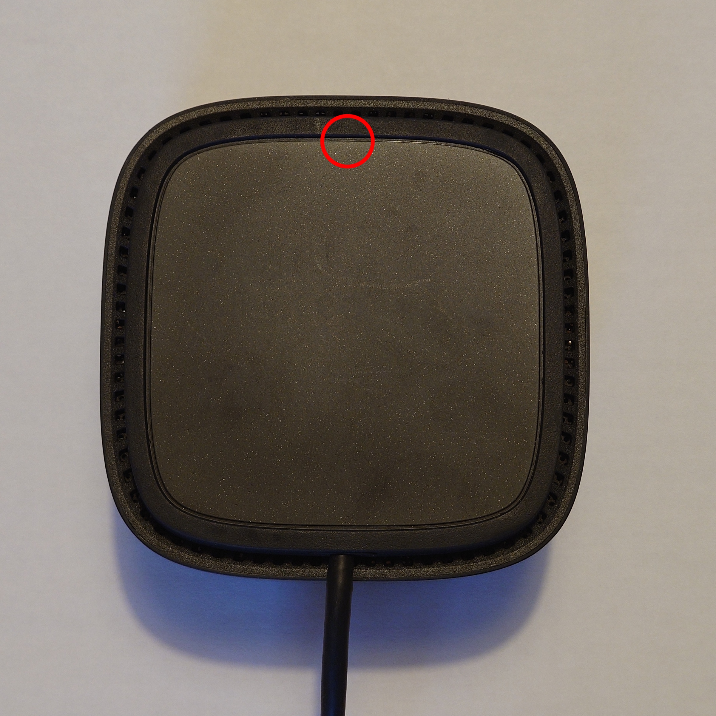
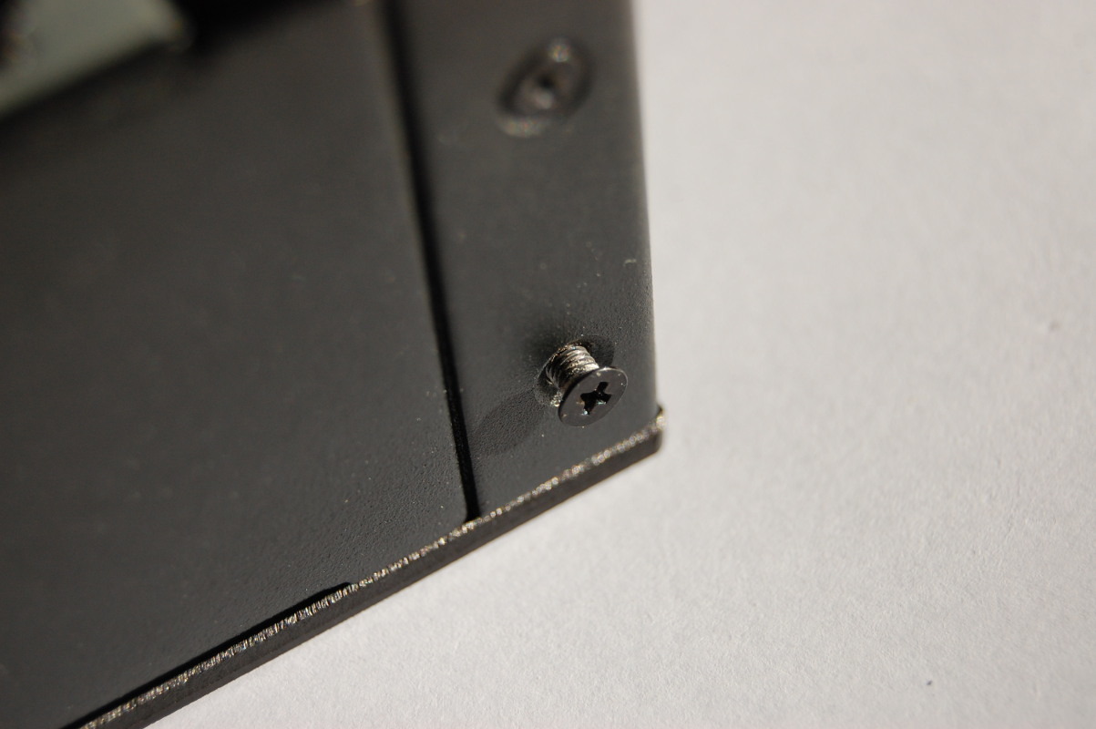
One Philips screw (on the base at rear) and the bottom slides off (gently lift and slide in the direction of the Thunderbolt cable).

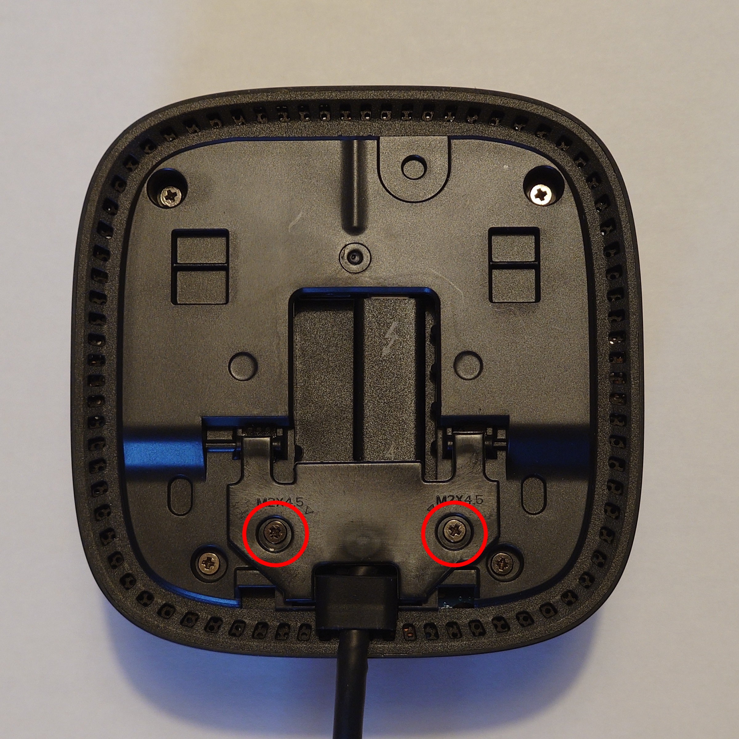
Remove the two Philips screws securing the collar over the Thunderbolt cable and swing the collar up. You can gently pull it to remove it from the base, however this is not required.

The Thunderbolt cable may appear “fixed” however it is just secured in place, so if you ever have a dock with a ruined Thunderbolt cable, do not throw it away as the cable can be replaced!

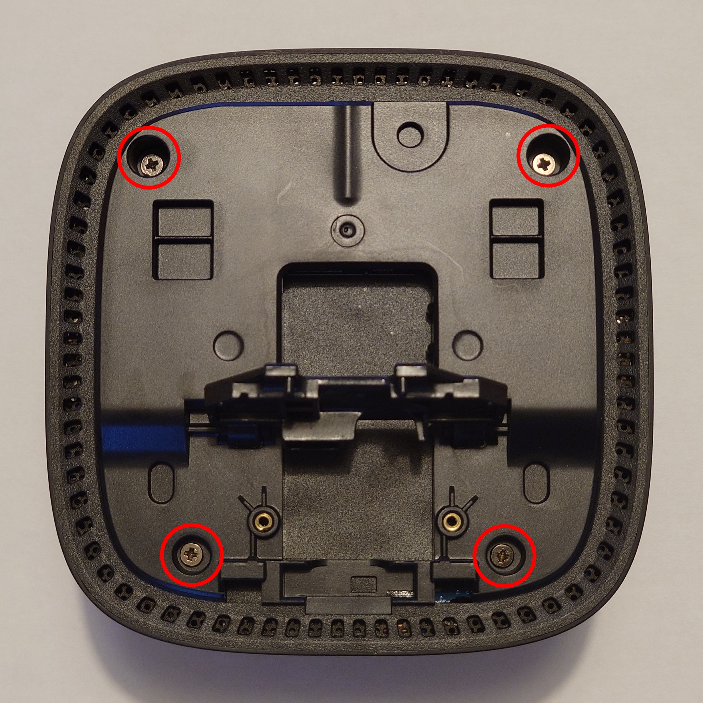
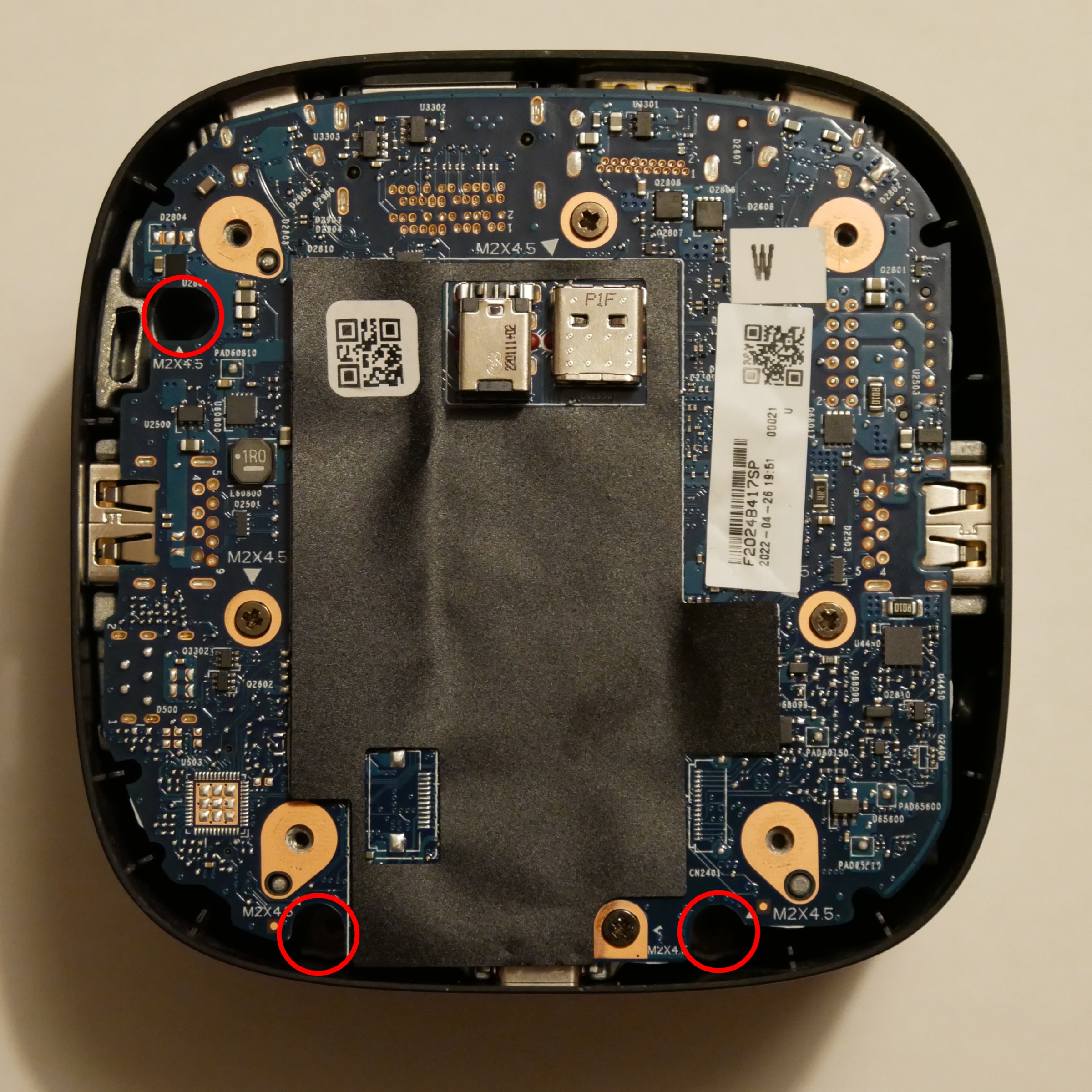
Remove the four Philips screws securing the bottom of the dock. There are no plastic clips around the outside of the base, so you can gently lift it out.

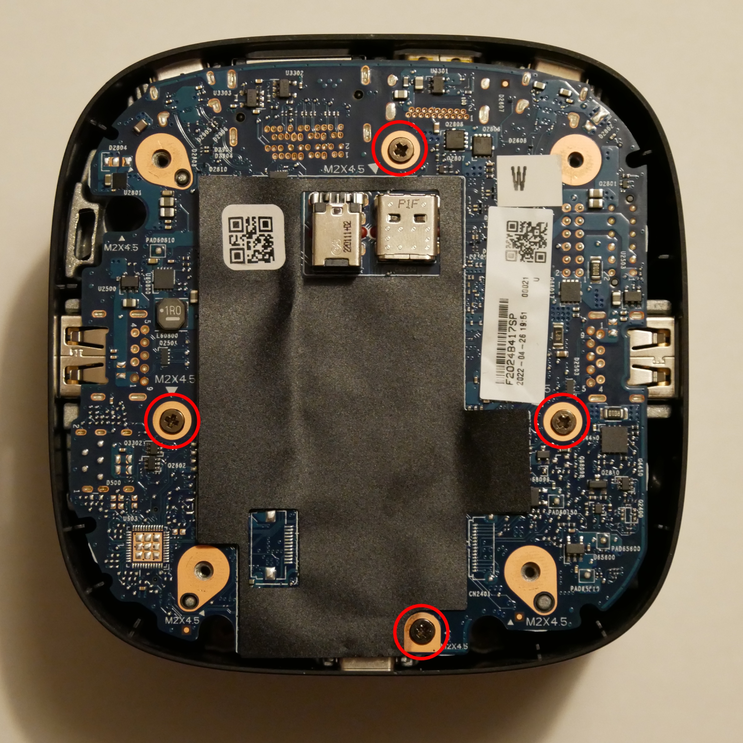
Remove the three recessed Philips screws to remove the dock components from the plastic housing.

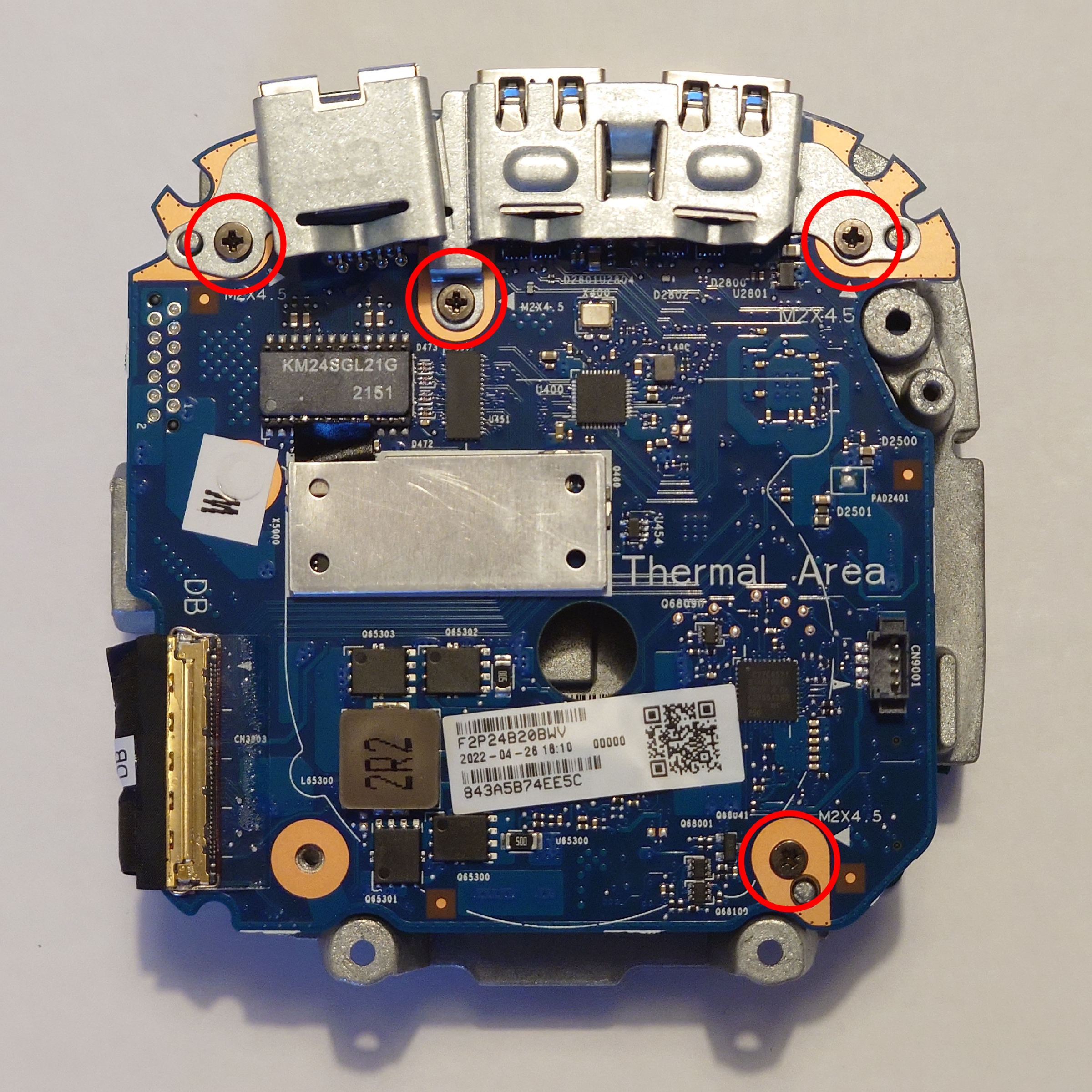
(Optional) If you need to release the bottom PCB (MB) from the heat spreader, remove the four Philips screws highlighted above. It is not necessary to remove these screws to remove the assembly from the plastic housing. There are several board-to-board connectors between the MB and DB PCBs inside the docking station; you need to remove the entire internal assembly from the plastic housing before you attempt to remove the bottom PCB.

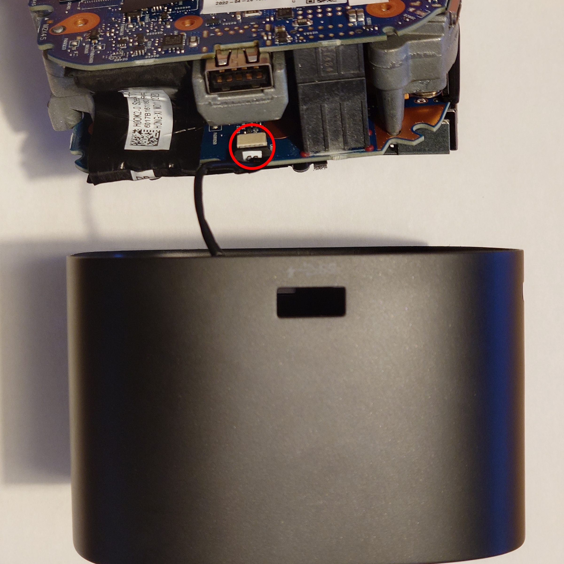
Be mindful of the connector to the top power button when removing the internal component assembly.

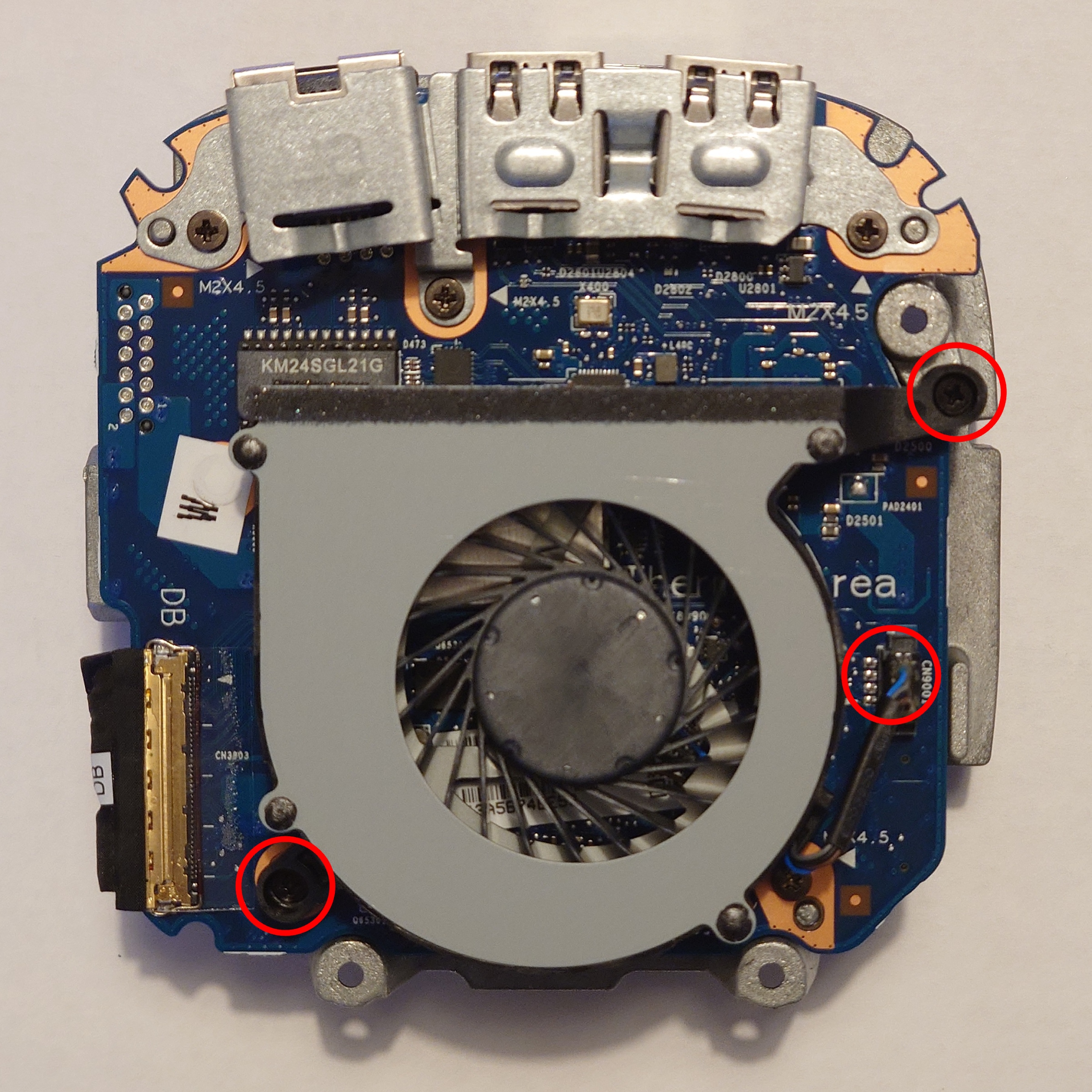
To replace the fan (Delta Electronics NS55B00-17E11), remove the two Philips screws and unplug it from the top PCB (DB).

To remove the top PCB (DB) from the heat spreader, remove the four Philips screws highlighted above.


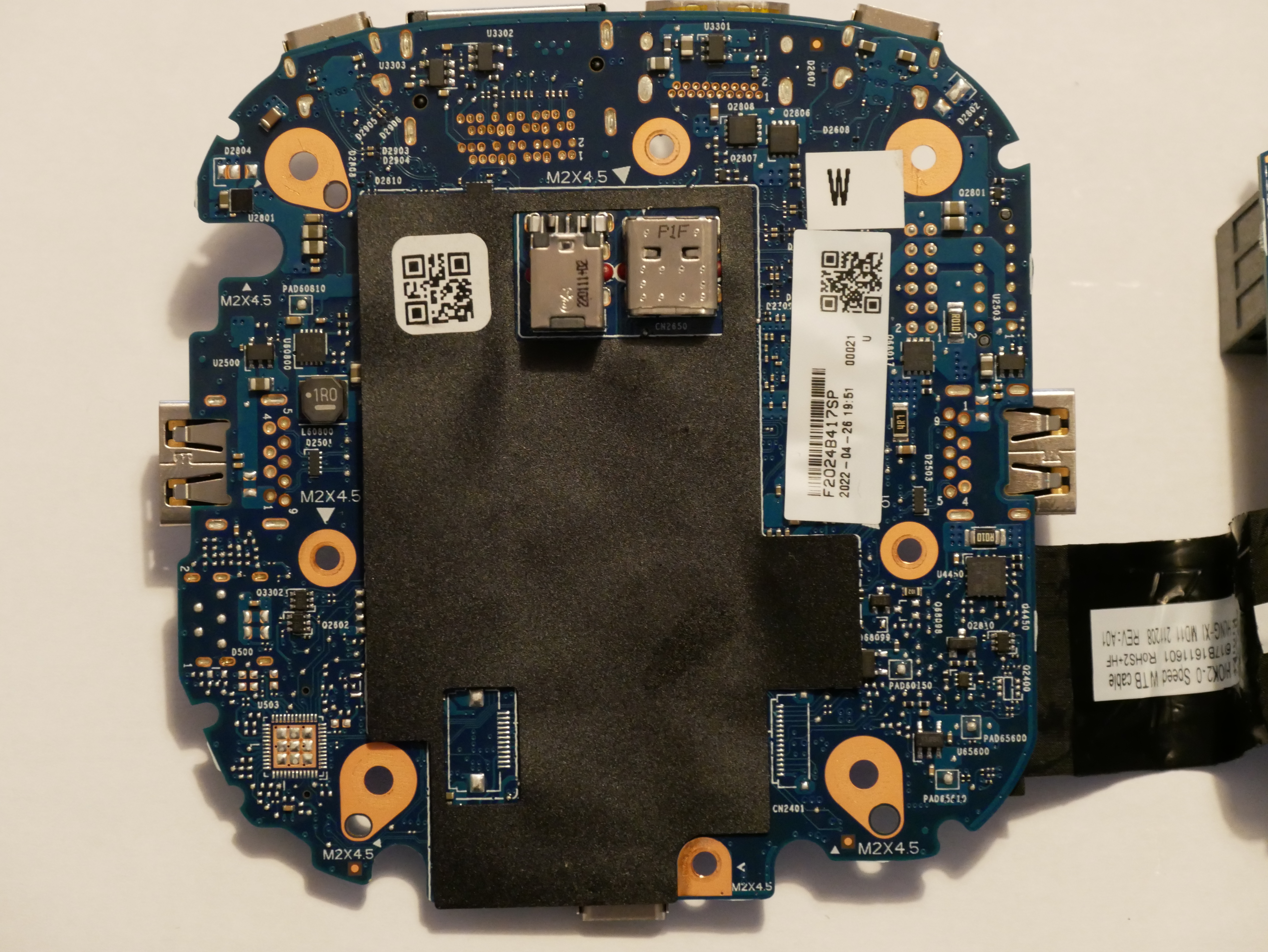
MB PCB bottom (full resolution PCB photo)

U3305: winbond W25Q80DVNIG (under black plastic, beside HP female power connector)

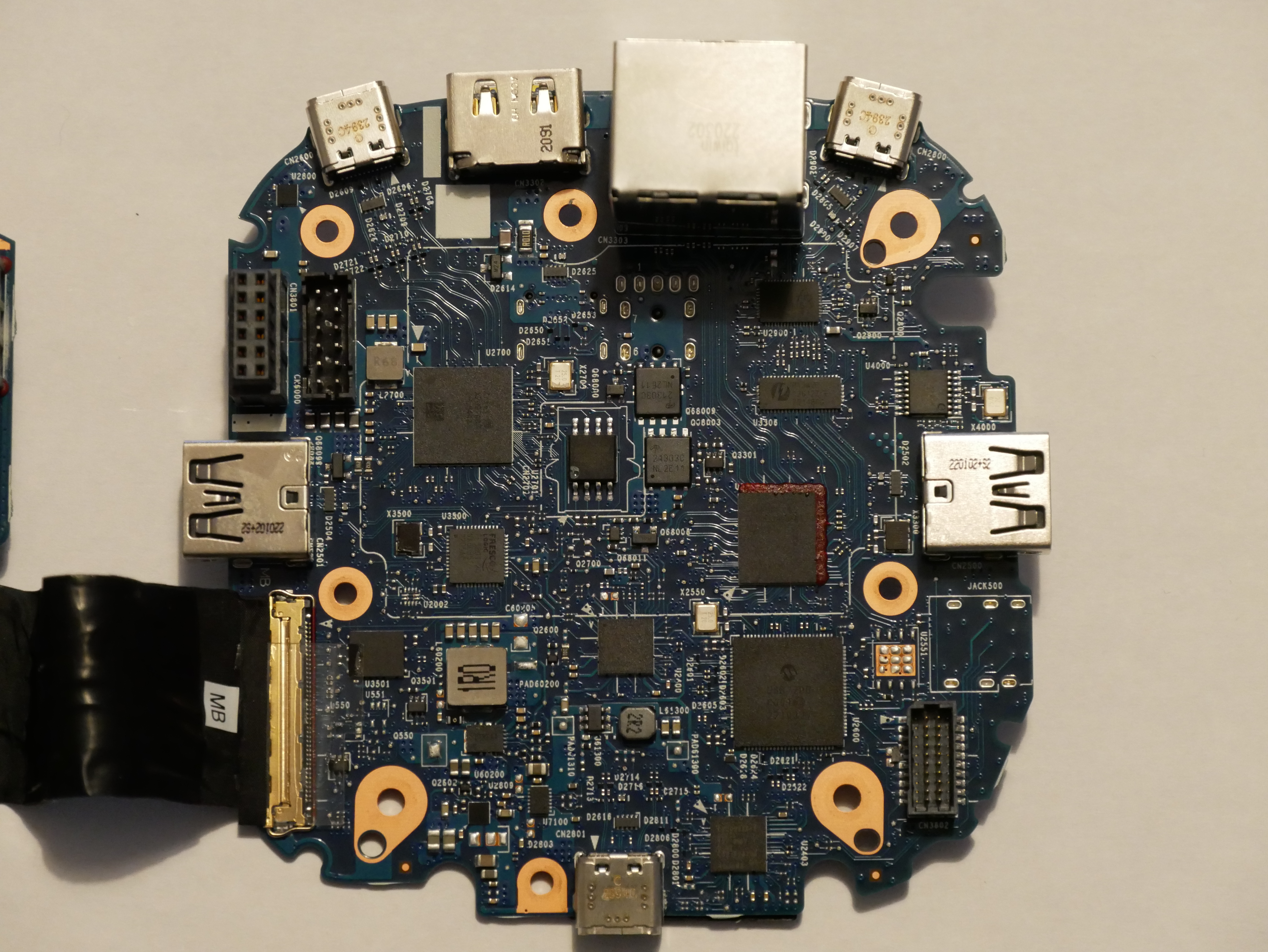
MB PCB top (full resolution PCB photo)

U2400/U2403: Infineon CYPD5236-96BZXI
U2600: Microchip USB7206
U????: Synaptics VMM5323BJGB1 (silk screen is obscured by underfill on my unit)
U3306: Pericom PI3WVR12412
U4000: Diodes Incorporated PI6C557-03BLE
U2900: Parade Tech PS8802
U2700: Intel JHL8440
U2701: winbond W25Q80DVSIG
U3500: fresco logic FL5801
U3501: winbond W25Q16JV

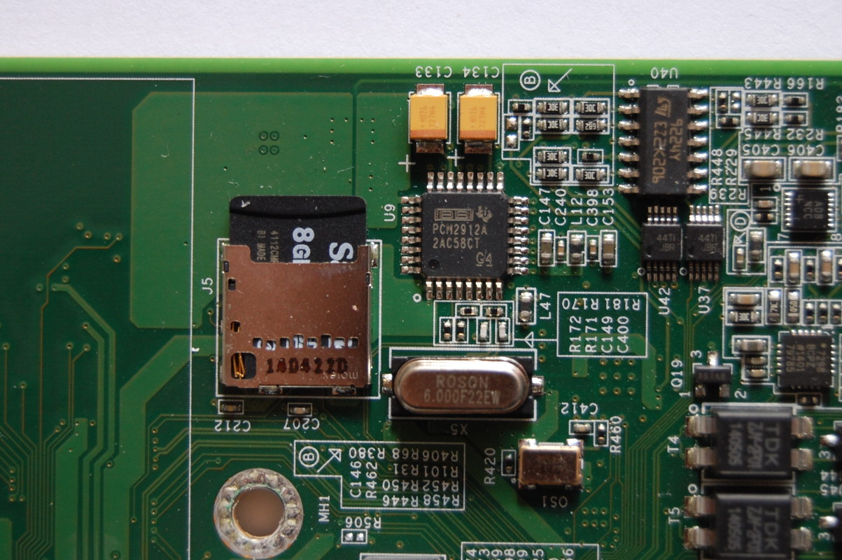
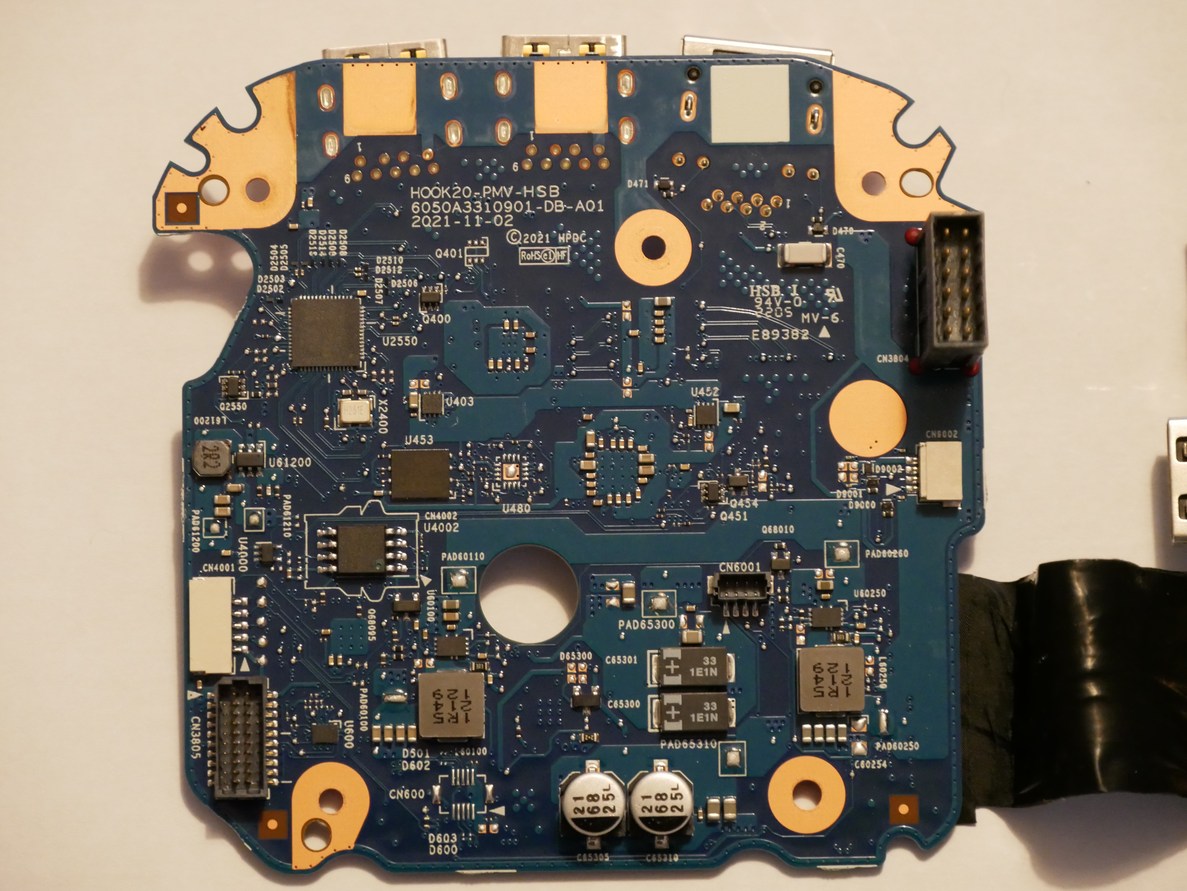
DB PCB bottom (full resolution PCB photo)

PCB silk screen:

HOOK20-PMV-HSB
6050A3310901-DB-A01
2021-11-02

U2550: Microchip USB5744
U453: winbond W25Q16JV
U4002: winbond W25Q64JVSIQ
CN9002: Power button header (power button PCB silk screen: 6050A3311201-PWRBUTTON-A01)

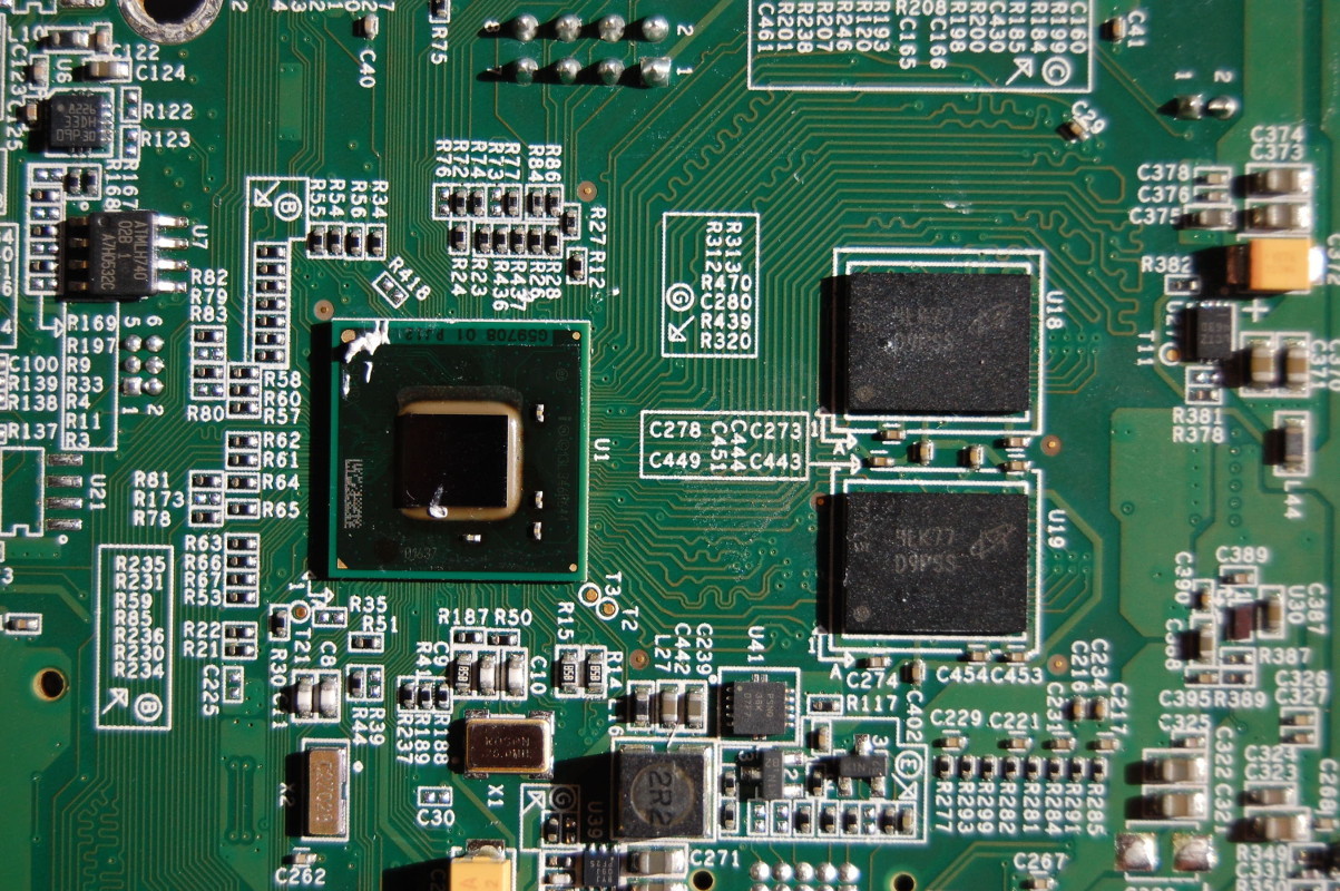
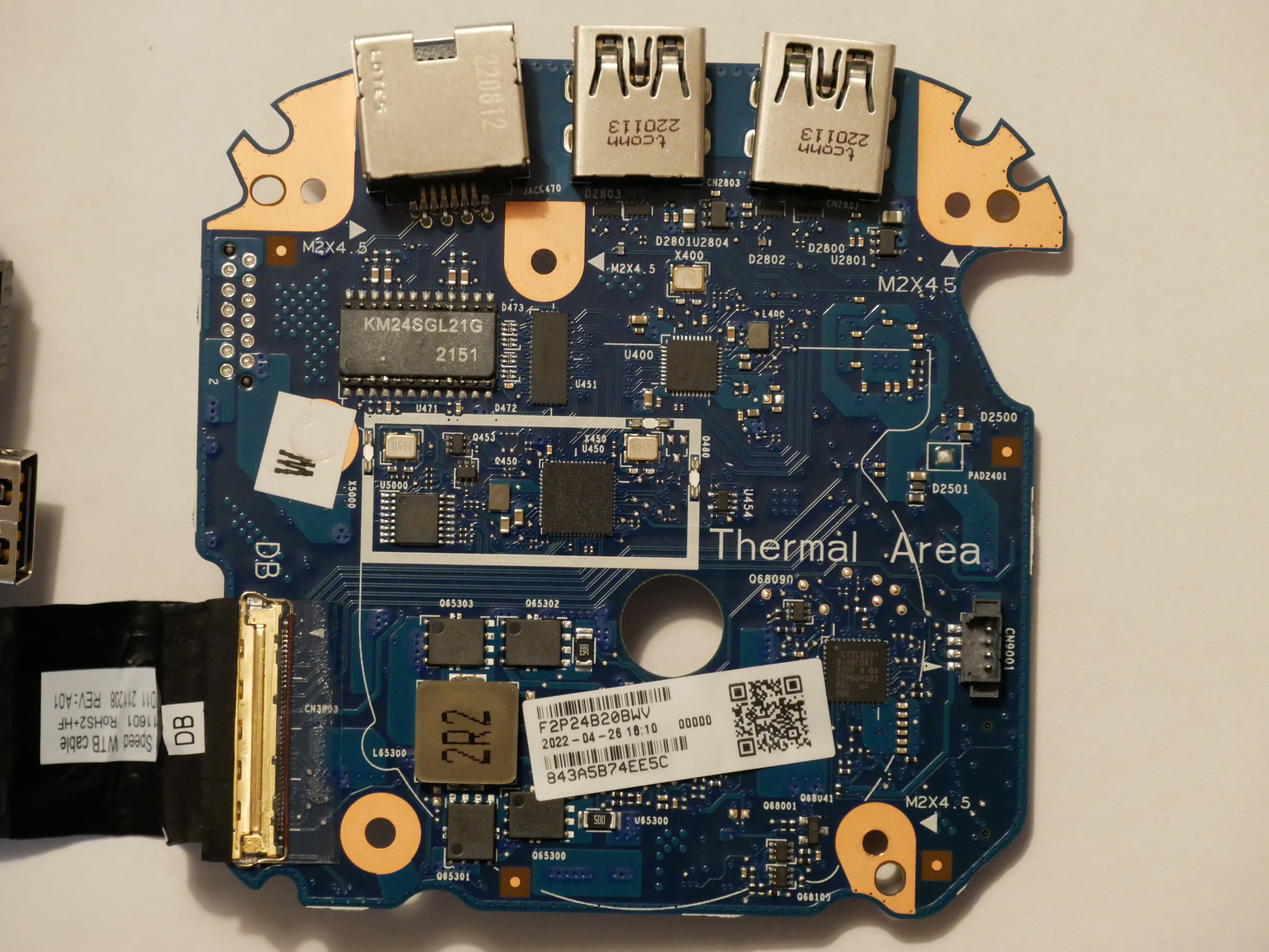
DB PCB top (full resolution PCB photo)

U451: P13L 2500ZHE 2136GG (PI3L?)
U400: Realtek RTL8153
U4003: Infineon CY7C65219-40LQXI
U5000: Diodes Incorporated PI6C557-03BLE
U450: Intel I225 (SLNNJ)
CN9001: Fan header

Fan: Delta Electronics NS55B00-17E11 (5V, 0.6A)

Power supply:
Output: 19.5V, 6.15A (120W)
Regulatory Model: TPN-DA19
HP Part No: L56786-013
HP Spare: L57117-001

Disabling Secure Boot on Intel Quark “secure SKU” silicon

Secure Boot is a bit like SELinux: people who use it really like it, and tell all their friends to use it. For everyone else, apart from those who don’t know about or even notice Secure Boot, it’s an annoyance that they almost immediately disable.

We’ve looked at the Intel DK200 from a hardware perspective before. Now it’s time to look at it from a software perspective. “Internet of Things Gateway” is pretty generic, so what can it actually do?

Following the instructions, I tried to register the system on Intel’s website so I could download the Wind River Intelligent Device Platform XT 2.0 SDK. I didn’t get very far:

No WindRiver SDK for you

Stormtrooper #1: This is not the product you’re looking for

Yeah… I guess this is what Mouser meant when they said the DK200 was End of Life.

Since this ships with the Linux Kernel, which is GPLv2 licensed, I believe Intel may be violating the GPL. Specifically:

Accompany it with a written offer, valid for at least three years, to give any third party, for a charge no more than your cost of physically performing source distribution, a complete machine-readable copy of the corresponding source code, to be distributed under the terms of Sections 1 and 2 above on a medium customarily used for software interchange

But I am not a lawyer, and I am not really that interested in starting a legal battle over the source code for an ancient version of Wind River Linux I am not interested in using anyway.

So let’s go try to build Yocto. The Intel rep did say there was a Yocto BSP coming “soon” but “soon” in Intel time seems kind of variable.

After some hiccups (Yocto needs python2 and GCC <6) I had built a Yocto image and put it on an SD card. Does it boot?

...no

…no

So we can’t boot Yocto because this is a “secure SKU” which means Secure Boot is enabled. Is there some way we can disable Secure Boot? What about updating the BSP to a newer version with Secure Boot disabled?

Back to hardware
If I’ve learned anything from messing around with electronics, you want to make a backup before you start modifying things. This is doubly so if the data in question is related to the booting process. It sucks to end up with a brick, so make a backup!

Taking a backup of flash

Taking a backup of flash

The Intel Quark guide mentions using a Dediprog SF100 to flash EDKII. I don’t have a Dediprog, but I do have an SPI programmer. Unfortunately, none of the Intel documentation I could find mentions the Dediprog header on the DK200, so I had to go hunting.

I traced the pins from the Winbond flash to header J23. J23 is only 8 pins, so trial and error with a multimeter to find the pin mapping wasn’t terrible:

J23 pinout

J23 pinout

Here’s the pinout of J23 in text form:

J23 pin 25Q64 pin Pin description
1 8 VCC
2 4 GND
3 1 /CS
4 6 CLK
5 2 DO
6 5 DI
7 Not connected
8 Not connected

/WP and HOLD pins on the 25Q64FV are not routed to J23, but they aren’t required for flashing.

With the pinout known, I could attach the SPI programmer to the header instead of using the chip clip:

J23 to ch341a SPI programmer

J23 to ch341a SPI programmer

I took a dump of the Winbond 25Q64FV and then for good measure desoldered the chip and read it again to confirm the images were exactly the same. It was strange because the image from the chip clip wasn’t identical. But, the image from the desoldered chip was identical to the image taken from J23, so we’re done here. I wrote the image to a new 25Q64FV and soldered that back onto the board.

Firmware disassembly
Disassembling the firmware which shipped on my DK200, we see that a Secure Boot certificate was created by WindRiver.

I assume that had I been able to download the WindRiver SDK, I would have been able to build and sign Secure Boot with my own certificates. Given that industrial customers spend a lot of time and money worrying about security, I was surprised to see that the Secure Boot certificate in the firmware was created by WindRiver China.

I did try to load up the image in IDA, but not being a power user of IDA, I couldn’t figure out how to get it to analyze the SPI dump, and gave up to try and compile the firmware from source.

Building the BSP

Being Intel, there are hundreds of pages you can read about developing for EDK2 and other really fun things, probably. I didn’t read them.

A document which I did end up reading religiously was the Intel ® QuarkTM SoC X1000 Board Support Package (BSP) Build and Software User Guide [PDF] which describes how to build all the firmware components needed to bring up the X1000 SoC. I found out there is actually a newer version of this document (1.2.1 instead of 1.1) and there are some important differences between the documents I want to get to later.

By building the firmware, we’re hoping for one of two outcomes:

  1. A firmware with our own Secure Boot certificates, or
  2. A firmware which has Secure Boot disabled

Version 1.1 of the BSP Build and Software User Guide includes a section on pages 29 and 30 on how to bundle your own db, kek, and pk certificates:

Page 29 and 30 condensed

Unfortunately if you follow the instructions and try to use a layout.conf which specifies these files, you’ll get an error because there’s no address specified for this data in the image:

I do have a reference file from WindRiver with Secure Boot certificates, so if I was really interested in making Secure Boot work as intended, I could have reverse engineered the address to store the certificates.

The certificates section of layout.conf was removed from the 1.2.1 revision of the BSP Build and Software User Guide. I guess since it no longer works, Intel decided to remove it from the documentation.

So, we can’t install our own Secure Boot certificates in the firmware. What happens if we just leave out the certificates section entirely and build it?

Error 37: Quark signature file not found

Right, so even though there’s now no certificate in the firmware bundle, we still can’t boot.

Interestingly, if you don’t partition the uSD or USB stick correctly, you end up with this pretty screen:

I never saw that in the stock firmware.

Hacking GRUB
So it seems that we can’t include our own Secure Boot certificate in the firmware, due to the sample layout.conf file missing the certificates section, and not knowing the appropriate address to store the certificates.

What if we dig into Error 37: Quark signature file not found a bit more?

If you look in the grub source code included in the BSP, you can see a giant ~1000KB patch that Intel has made to the original upstream code to support the Quark platform.

If you grep for “Quark signature file not found” you’ll find it was added in stage2/common.c:
diff --git a/stage2/common.c b/stage2/common.c
index e96bec2..e122745 100644
--- a/stage2/common.c
+++ b/stage2/common.c
@@ -88,6 +88,8 @@ char *err_list[] =
[ERR_UNRECOGNIZED] = "Unrecognized command",
[ERR_WONT_FIT] = "Selected item cannot fit into memory",
[ERR_WRITE] = "Disk write error",
+ [ERR_QUARK_VERIFICATION] = "Quark signature verification failed",
+ [ERR_SGN_FILE_NOT_FOUND] = "Quark signature file not found",
};

If you grep for ERR_SGN_FILE_NOT_FOUND you’ll find it’s in the following files:
./work/efi/ia32/loader/linux.c:410: errnum = ERR_SGN_FILE_NOT_FOUND;
./work/efi/ia32/loader/linux.c:732: errnum = ERR_SGN_FILE_NOT_FOUND;
./work/efi/quark/boot_settings.c:190: errnum = ERR_SGN_FILE_NOT_FOUND;

Going back to Intel’s modifications to grub, we can see what they added:

It takes a bit of searching, but if you strip out all of the grub_quark_secure logic from linux.c and boot_settings.c, you end up with…

Ta-da! I can boot Yocto Linux

No more Secure Boot!

At the end of the day, the Quark X1000 is an x86: “secure SKU” is nothing but a fuse setting.

The comment should read:

Determine whether or not grub should enforce Secure Boot.

In our case, this is not a mandatory option 😉

Special offer for DK200 owners
As shown above, it is possible to modify the Intel sources to disable Secure Boot. If there are other people have a DK200 from Intel and are interested in running a firmware without Secure Boot, leave a comment with your contact details. Upon request, I can provide a firmware image* with generic Ethernet MAC addresses for you to flash. Note that this firmware is specific to the DK200 (Clanton Hill) hardware.

* No warranty, express or implied, provided for said firmware image. You flash at your own risk!

Intel DK200 IoT Gateway

Earlier this year I was at a conference and heard from other attendees that the Intel booth was giving away IoT gateways. Never one to turn down free conference swag, I hurried over to the Intel booth and was told to pick up a gateway out of a pallet of boxes just delivered (and rapidly disappearing).

The Intel IoT gateway series is codenamed Moon Island, but the design targeting the transportation market is codenamed Clanton Hill. Clanton Hill known to us mortals as the “Intel DK200 Series Gateway Solution for the Internet of Things (IoT)” quite the mouthful.

Let’s get down to it.

Availability
Unless you happen to be at a conference where Intel reps are handing these out like candy, I don’t think it’s practical to try and buy one yourself:

dk200_mouser

Some interesting details to note about this product:

  1. Although released in 2014, the DK200 still costs more than the new MacBook (3,712.50 EUR versus 3,199 EUR)
  2. It’s End Of Life

When a low volume product goes EOL and you still have stock, I guess giving it away at conferences is the next logical step.

Hardware Specifications
The DK200 (datasheet) is targeted toward the transportation industry, and it really shows in the appearance of the device:

Only available in 'Cosmic Black'

Only available in ‘Cosmic Black’

I don’t work in the transportation industry, and have never seen connectors that look like this before. They’re very well made, and I suspect probably do a good job of keeping dust, dirt, and debris out of the ports. Since I don’t wish to make a mess by throwing dirt and debris at it, I’m going to have to trust the engineers who designed it.

The build quality is quite good, as one might expect from a device selling for 3,700 EUR. Nearly every screw is secured with loctite to prevent vibration from loosening them:

DK200 screw with loctite

No pentalobe nonsense here

However, I was surprised to find that despite all the physical hardening applied to the enclosure, I couldn’t find any information on an IP rating. In fact the top and bottom of the case don’t appear to offer any additional dust or water seal. There’s clearly been a lot of thought put into the design of this enclosure to withstand vibration and dirt, so it’s strange that there doesn’t seem to be water protection of any kind.

Processor
The Intel Quark series SoC was introduced in late 2013. The X1020D in the DK200 is a single core SoC based around a 80486 core running at 400MHz, with modern I/O and memory.

dk200_x1020d

In 2014 a leaked product roadmap suggested a successor to the X1000 series named “Dublin Bay” to be released in 2015. Then news emerged that “Dublin Bay” had been cancelled, to be replaced by “Liffy Island” and “Seal Beach” which would be released in 2015. As of late 2016 Intel has not released a direct successor to the X1000 series, and there is no new news of “Liffy Island” or “Seal Beach” being cancelled (or released). So it’s anyone’s guess whether Intel is still even interested in the IoT gateway market.

Storage
The DK200 doesn’t include any of the typical storage buses like SATA, NVMe, or NAND (EMMC). This is not overly surprising given the embedded nature of the hardware (requiring lower power) and the simplicity of the Quark processor.

The only storage option is a micro SDHC card, and the DK200 includes an 8GB class 4 micro SD card:
dk200_sdhc

Given that it’s a class 4 card, the performance is quite poor. Use of an SD card for storage isn’t a bad decision per se, but the DK200 uses ext3 for the root partition. Ext3 is not a flash aware filesystem. SD cards have only basic wear leveling, and ext3 has no wear leveling. So it hardly seems like the appropriate combination of storage and filesystem for a headless embedded device with an expected lifetime of 5-10 years.

Input and output

  • Dual 100Mbit Ethernet controllers
  • 3 x USB 2.0 host and 1x device
  • Audio in/out
  • CAN bus
  • RS-232
  • GPIO
  • 1x half-height mini PCI-e slot (populated with Intel 7260)
  • 1x full-height mini PCI-e slot (unpopulated; for 3G modem/GPS)

The Intel documentation also mentions ZigBee, however this is an external device, presumably attached via the USB bus.

Power consumption
Development platforms aren’t known for being highly optimised devices. They often include extra I/O which would not necesssarily be included in the final product, and as such do not have the same energy efficiency as a finished product.

This being said, I was quite surprised that a device intended for 24/7 operation in an embedded environment, and especially serving the “Internet of Things” market, could be so energy inefficient. Issuing a poweroff command in Linux results in the platform going into an S5 (shutdown) state. I was surprised to discover that the energy consumption in the S5 state is 2W. This seems quite high for a device which includes an ignition input for automatic power-on and shutdown.

When booting, the device peaks at 7.9W consumption, while the idle power consumption is 7.5W. This is almost certainly due to the added peripherals as the TDP of the Quark processor is only 2W.

It’s difficult to see how Intel expects the Quark platform to compete with ARM. My PandaBoard ES, an ARM-based development board from 2011, peaks at 4W, idles at 2W, and draws nothing when off. Now some might argue that comparing an ARM board from 2011 with an Intel IoT gateway from 2014 isn’t valid, but they do have a lot of similar features. Now, I will grant that the PandaBoard is not in a rugged enclosure with fancy connectors, but since it cost 95% less than the DK200 does, there’s some room in the budget for an enclosure and funky connectors. And, since Texas Instruments has stopped making OMAP chips, the PandaBoard gets about the same amount of vendor support as the DK200!

Software

I will be exploring the software of the DK200 in a follow up post. Stay tuned!