The Meraki MS425 series switches (codename “Hungry Hungry Hippo”) offer 16 or 32 ports of 10Gbit SFP+ Ethernet, two 40Gbit QSFP+ stacking ports, and a Gigabit Ethernet management port.
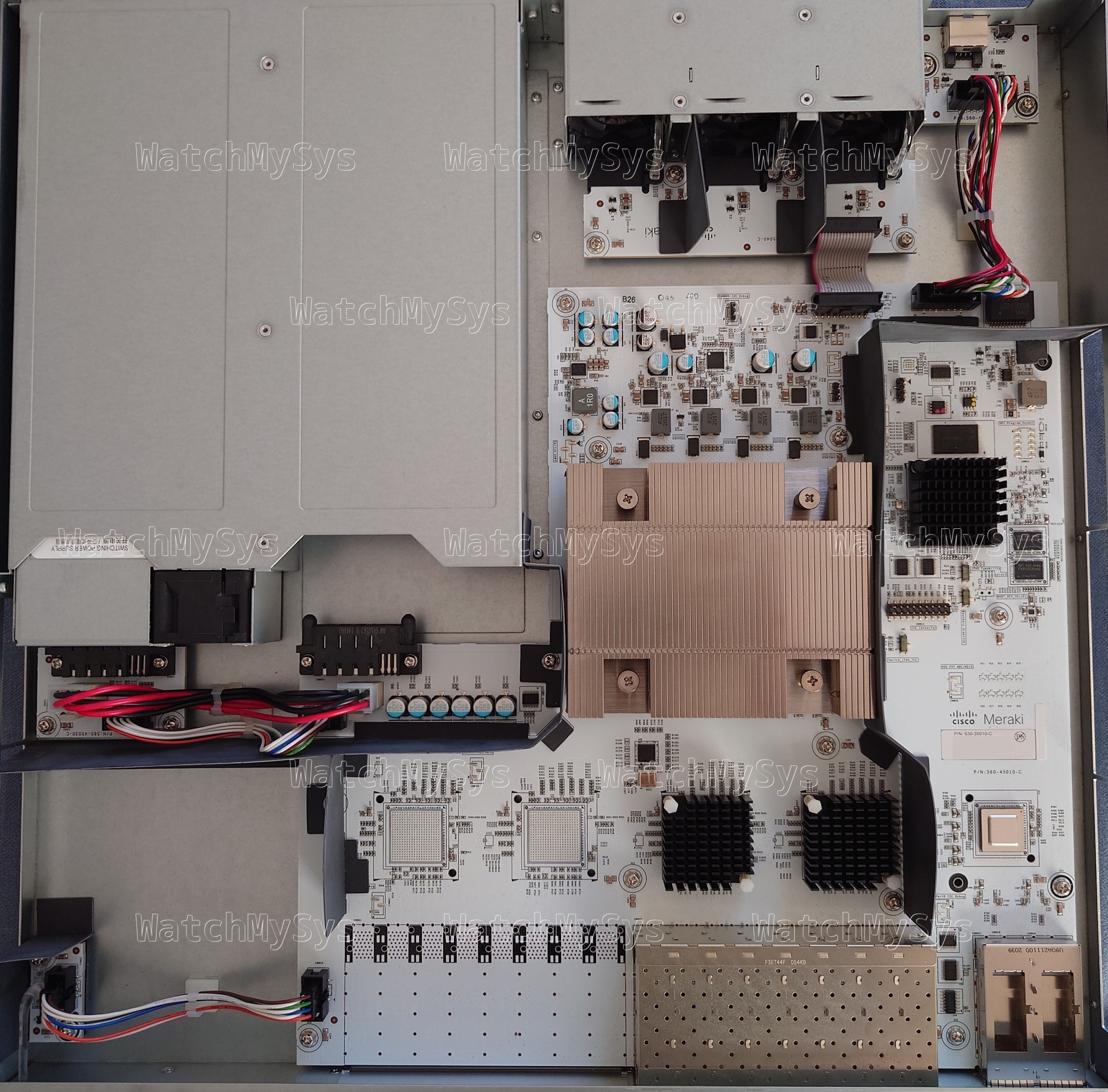
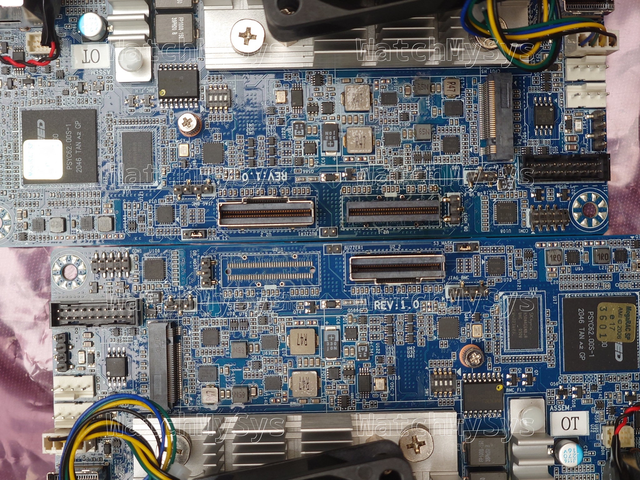
Meraki MS425-16 internal view
The MS425 was discontinued in June 2024, and is too old to support secure boot.
Here is a quick summary of the MS425 specs:
- Broadcom BCM56854 “Trident II” ASIC
- Broadcom BCM5862x “StrataGX” management CPU
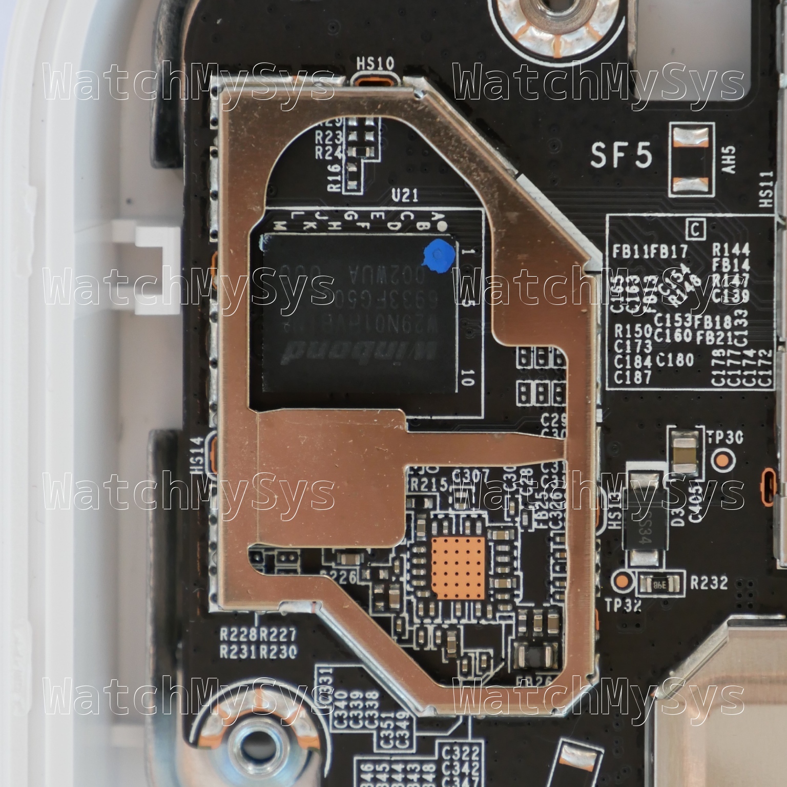
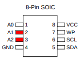
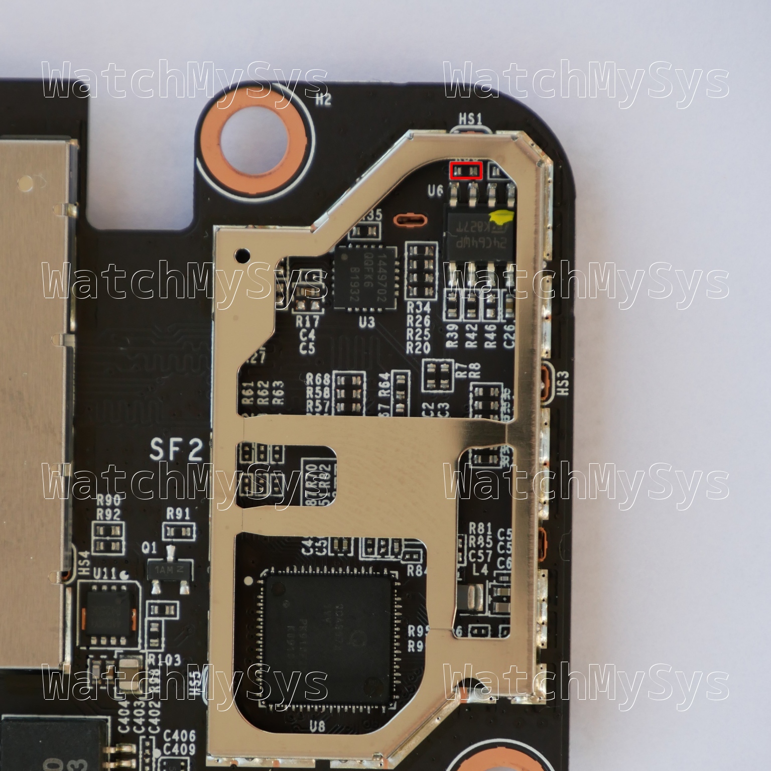
- 16MB of SPI flash (MX25L12805D)
- 2GB DDR3 RAM (soldered)
- 1024MB NAND flash (Micron MT29F8G08ABACA; PDF datasheet)
- MA-PWR-250WAC (identical to PWR-C2-250WAC)
The UART header in the MS425 is CONN7 (silk screen: UART Console) and follows the standard Meraki UART pinout (1: 3.3V Vcc, 2: Tx, 3: Rx, 4: GND) at 115200 baud.
The MS425-16 uses the same PCB as the MS425-32, but missing 16 SFP+ cages and two PHYs. This is the same technique Meraki used for the MS420-24 model.
The stock Meraki boot process uses u-boot on SPI to load a “bootkernel” (also from SPI), which then initializes NAND and using kexec boots the main firmware. The firmware layout follows the standard Meraki practice of having A/B firmware images: bootkernel1, bootkernel2, part.safe, part.old.
The firmware layout on SPI is:
0x000000-0x100000 : "uboot"
0x100000-0x800000 : "bootkernel1"
0x800000-0xf00000 : "bootkernel2"
Unlike the MS350, the management plane is not an x86 CPU, but a Broadcom “StrataGX” ARMv7. The MS425 runs the same firmware release (switch-arm) as the MS210/MS225/MS250 series.
PCI devices present:
00:00.0 PCI bridge: Broadcom Inc. and subsidiaries Device 8025 (rev 12)
01:00.0 Ethernet controller: Broadcom Inc. and subsidiaries Device b854 (rev 03)
The Broadcom SDK series implements the packet engine in userspace, using the GPL-licensed linux_kernel_bde and linux_user_bde kernel modules to interface with the ASIC. In the Meraki firmware, the packet engine is a component of the userspace click daemon, which loads the bcm_click shared object during click router initialisation.
Similar to the MS420, the three 40mm system fans in the MS425 are controlled by an onsemi ADT7473 (PDF datasheet). The MS425 fans have a Meraki part number: MA-FAN-18K (P/N 680-29010) and contain the Delta FFB0412UHN-C (PDF datasheet). These are identical to the Cisco FAN-T1, which can be purchased for considerably less than the Meraki branded part.
The MS425 accepts two hot-swap power supplies (model MA-PWR-250WAC, P/N 640-20010), which in my units are Delta model DPS-250AB-86 with 12V/20.83A output. Note that the MA-PWR-250WAC is physically and electrically compatible with PWR-C2-250WAC. Higher wattage power supplies like the PWR-C2-640WAC and PWR-C2-1025WAC will also power the MS425.
Idle power consumption:
MS425-16: 72W
MS425-32: 78W
Interesting to note is that the Trident II ASIC found in the MS425 supports VxLAN, however this feature is absent from Meraki’s datasheet and does not appear to be supported by their firmware. Apart from 40Gbit stacking ports, there is not much to be gained from the Trident II in the MS425 over the Trident+ in the MS420: idle power consumption is slightly lower, and it is still supported (see note below).
Meraki have chosen to EoL all of their Broadcom based switches. Being a Broadcom design, the MS425 was axed from the product portfolio on 2024-06-24. The MS425 will continue to receive limited software support from Meraki until Q3 2029. Big “we cancelled all our contracts with Broadcom and are now a Marvell/Catalyst shop” energy.
The GPL source code for the MS425 was requested from Meraki in December 2023, and at the time of writing Meraki has not provided any of the requested source code.
“[F]ulfilling your requests are an important priority for [Meraki]” so I am sure they will comply with their license obligations… Any day now… Just wait for it… It is almost as if they know that providing the GPL source code would enable people to re-use claimed/EOL products and are avoiding doing that. 🤔
| Model | Meraki Board | Part number |
|---|---|---|
| MS425-16 | Hungry Hungry Hippo | 600-45010 |
| MS425-32 | Hungry Hungry Hippo | 600-45015, 600-45020 |