2.5Gbit Ethernet is finally at an affordable price, but modern platforms do not offer much in the way of upgrade paths. Desktop PC motherboards typically dedicate all PCIe lanes to graphics or NVMe, leaving you with tough choices to make if you want to upgrade your network card. The situation is even worse for small form factor and embedded devices.
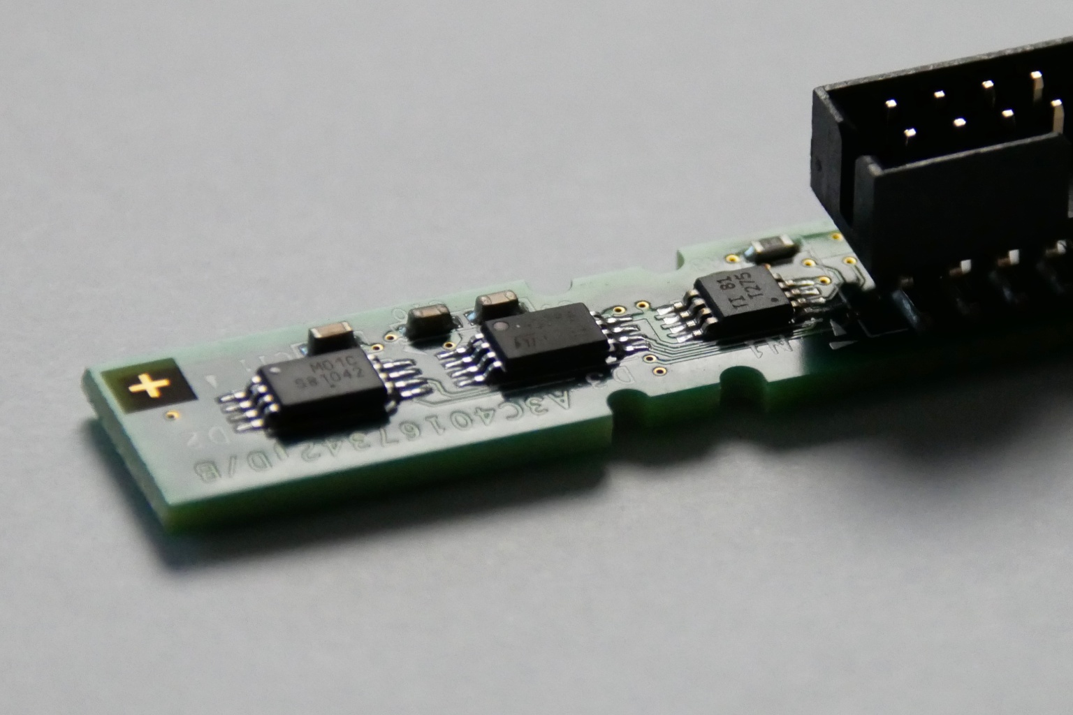
Or so I thought, until I discovered an M.2 A+E key 2.5Gbit Ethernet card based on the Realtek RTL8125B.
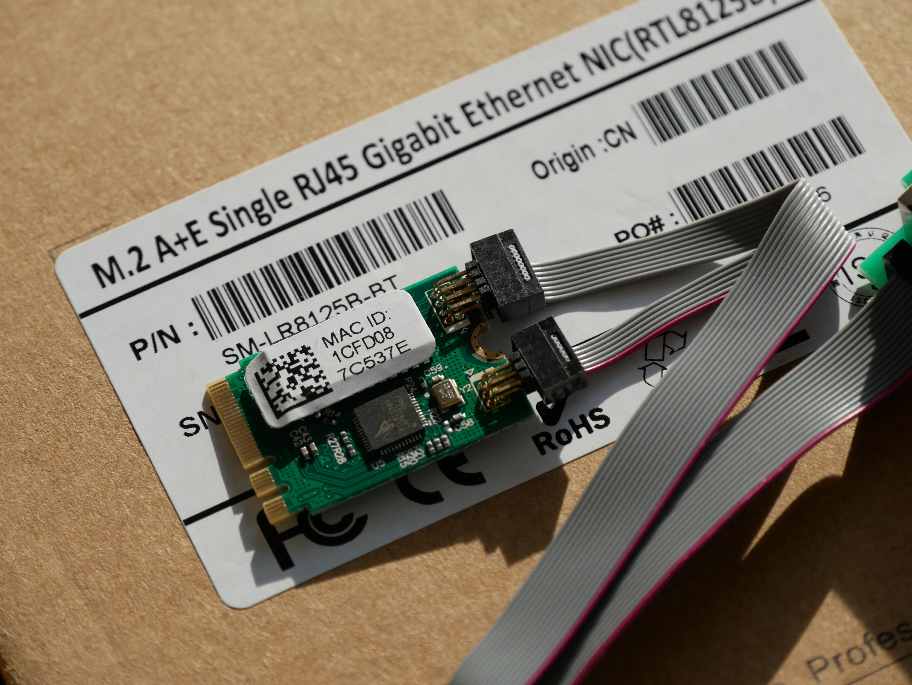
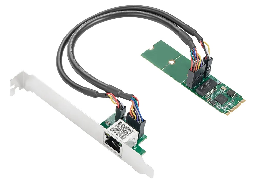
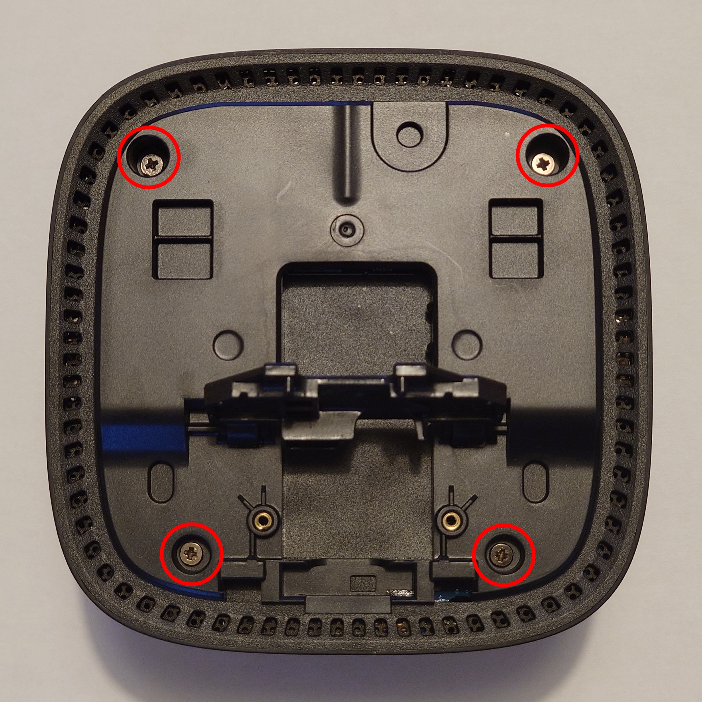
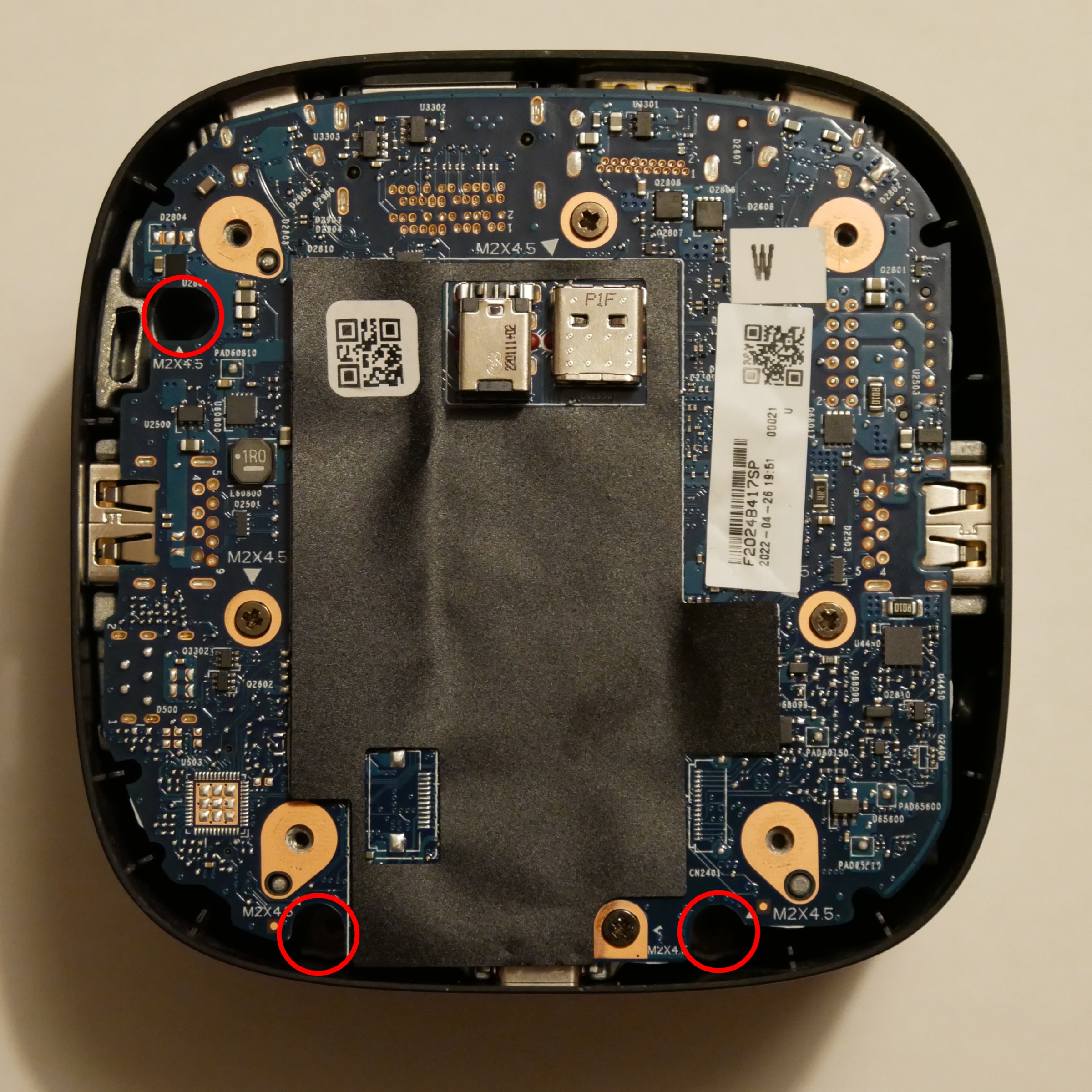
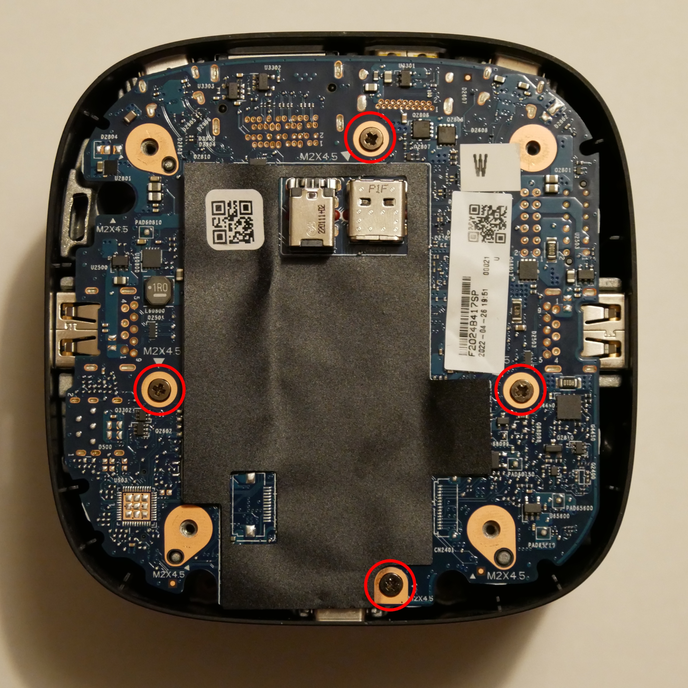
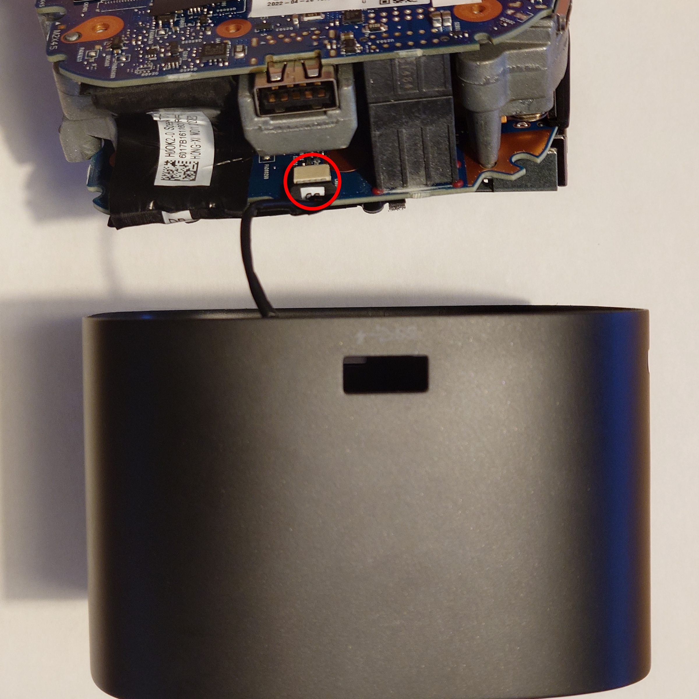
This tiny M.2 2230 card can be installed in the M.2 WiFi slot present on many motherboards. If you were not already using WiFi, this means you have a “free” upgrade path to 2.5Gbit Ethernet, without sacrificing any higher bandwidth PCIe slots. Better still, M.2 A+E keyed slots are commonly available in the “TinyMiniMicro” segment of small-form-factor PCs. This allows you to install 2.5Gbit networking in the Asus PN50, or an HP T640 thin client. You can also find mini-PCIe to M.2 A+E adapters, allowing you to install the NIC in a device that predates M.2.
Also attractive is the price, I bought two for 15.70€/piece (including VAT and shipping) from AliExpress. This is only a small premium over what a full-size PCIe card with an RTL8125B costs (typically around 13€).
02:00.0 Ethernet controller: Realtek Semiconductor Co., Ltd. RTL8125 2.5GbE Controller (rev 05)
        Subsystem: Realtek Semiconductor Co., Ltd. Device 0123
        Control: I/O+ Mem+ BusMaster+ SpecCycle- MemWINV- VGASnoop- ParErr- Stepping- SERR+ FastB2B- DisINTx+
        Status: Cap+ 66MHz- UDF- FastB2B- ParErr- DEVSEL=fast >TAbort- <TAbort- SERR- <PERR- INTx-
        Latency: 0, Cache Line Size: 64 bytes
        Interrupt: pin A routed to IRQ 50
        IOMMU group: 8
        Region 0: I/O ports at e000 [size=256]
        Region 2: Memory at fe910000 (64-bit, non-prefetchable) [size=64K]
        Region 4: Memory at fe920000 (64-bit, non-prefetchable) [size=16K]
        Expansion ROM at fe900000 [disabled] [size=64K]
        Capabilities: [40] Power Management version 3
                Flags: PMEClk- DSI- D1+ D2+ AuxCurrent=375mA PME(D0+,D1+,D2+,D3hot+,D3cold+)
                Status: D0 NoSoftRst+ PME-Enable- DSel=0 DScale=0 PME-
        Capabilities: [50] MSI: Enable- Count=1/1 Maskable+ 64bit+
                Address: 0000000000000000  Data: 0000
                Masking: 00000000  Pending: 00000000
        Capabilities: [70] Express (v2) Endpoint, MSI 01
                DevCap: MaxPayload 256 bytes, PhantFunc 0, Latency L0s <512ns, L1 <64us
                        ExtTag- AttnBtn- AttnInd- PwrInd- RBE+ FLReset- SlotPowerLimit 0W
                DevCtl: CorrErr+ NonFatalErr+ FatalErr+ UnsupReq+
                        RlxdOrd- ExtTag- PhantFunc- AuxPwr- NoSnoop-
                        MaxPayload 128 bytes, MaxReadReq 4096 bytes
                DevSta: CorrErr+ NonFatalErr- FatalErr- UnsupReq+ AuxPwr+ TransPend-
                LnkCap: Port #0, Speed 5GT/s, Width x1, ASPM L0s L1, Exit Latency L0s unlimited, L1 <64us
                        ClockPM+ Surprise- LLActRep- BwNot- ASPMOptComp+
                LnkCtl: ASPM Disabled; RCB 64 bytes, Disabled- CommClk+
                        ExtSynch- ClockPM+ AutWidDis- BWInt- AutBWInt-
                LnkSta: Speed 5GT/s, Width x1
                        TrErr- Train- SlotClk+ DLActive- BWMgmt- ABWMgmt-
                DevCap2: Completion Timeout: Range ABCD, TimeoutDis+ NROPrPrP- LTR+
                         10BitTagComp- 10BitTagReq- OBFF Via message/WAKE#, ExtFmt- EETLPPrefix-
                         EmergencyPowerReduction Not Supported, EmergencyPowerReductionInit-
                         FRS- TPHComp+ ExtTPHComp-
                         AtomicOpsCap: 32bit- 64bit- 128bitCAS-
                DevCtl2: Completion Timeout: 50us to 50ms, TimeoutDis- LTR- 10BitTagReq- OBFF Disabled,
                         AtomicOpsCtl: ReqEn-
                LnkCap2: Supported Link Speeds: 2.5-5GT/s, Crosslink- Retimer- 2Retimers- DRS-
                LnkCtl2: Target Link Speed: 5GT/s, EnterCompliance- SpeedDis-
                         Transmit Margin: Normal Operating Range, EnterModifiedCompliance- ComplianceSOS-
                         Compliance Preset/De-emphasis: -6dB de-emphasis, 0dB preshoot
                LnkSta2: Current De-emphasis Level: -3.5dB, EqualizationComplete- EqualizationPhase1-
                         EqualizationPhase2- EqualizationPhase3- LinkEqualizationRequest-
                         Retimer- 2Retimers- CrosslinkRes: unsupported
        Capabilities: [b0] MSI-X: Enable+ Count=32 Masked-
                Vector table: BAR=4 offset=00000000
                PBA: BAR=4 offset=00000800
        Capabilities: [d0] Vital Product Data
                Not readable
        Capabilities: [100 v2] Advanced Error Reporting
                UESta:  DLP- SDES- TLP- FCP- CmpltTO- CmpltAbrt- UnxCmplt- RxOF- MalfTLP- ECRC- UnsupReq- ACSViol-
                UEMsk:  DLP- SDES- TLP- FCP- CmpltTO- CmpltAbrt- UnxCmplt- RxOF- MalfTLP- ECRC- UnsupReq- ACSViol-
                UESvrt: DLP+ SDES+ TLP- FCP+ CmpltTO- CmpltAbrt- UnxCmplt- RxOF+ MalfTLP+ ECRC- UnsupReq- ACSViol-
                CESta:  RxErr- BadTLP- BadDLLP- Rollover- Timeout- AdvNonFatalErr-
                CEMsk:  RxErr- BadTLP- BadDLLP- Rollover- Timeout- AdvNonFatalErr+
                AERCap: First Error Pointer: 00, ECRCGenCap+ ECRCGenEn- ECRCChkCap+ ECRCChkEn-
                        MultHdrRecCap- MultHdrRecEn- TLPPfxPres- HdrLogCap-
                HeaderLog: 00000000 00000000 00000000 00000000
        Capabilities: [148 v1] Virtual Channel
                Caps:   LPEVC=0 RefClk=100ns PATEntryBits=1
                Arb:    Fixed- WRR32- WRR64- WRR128-
                Ctrl:   ArbSelect=Fixed
                Status: InProgress-
                VC0:    Caps:   PATOffset=00 MaxTimeSlots=1 RejSnoopTrans-
                        Arb:    Fixed- WRR32- WRR64- WRR128- TWRR128- WRR256-
                        Ctrl:   Enable+ ID=0 ArbSelect=Fixed TC/VC=01
                        Status: NegoPending- InProgress-
        Capabilities: [168 v1] Device Serial Number 01-00-00-00-68-4c-e0-00
        Capabilities: [178 v1] Transaction Processing Hints
                No steering table available
        Capabilities: [204 v1] Latency Tolerance Reporting
                Max snoop latency: 0ns
                Max no snoop latency: 0ns
        Capabilities: [20c v1] L1 PM Substates
                L1SubCap: PCI-PM_L1.2+ PCI-PM_L1.1+ ASPM_L1.2+ ASPM_L1.1+ L1_PM_Substates+
                          PortCommonModeRestoreTime=150us PortTPowerOnTime=150us
                L1SubCtl1: PCI-PM_L1.2- PCI-PM_L1.1- ASPM_L1.2- ASPM_L1.1-
                           T_CommonMode=0us LTR1.2_Threshold=306176ns
                L1SubCtl2: T_PwrOn=150us
        Capabilities: [21c v1] Vendor Specific Information: ID=0002 Rev=4 Len=100
        Kernel driver in use: r8169
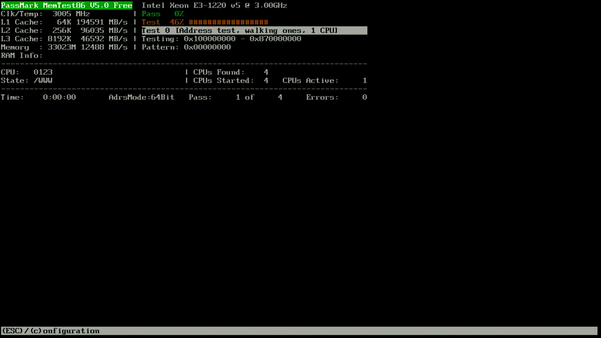
iperf3 testing shows that we can achieve consistent results over 2.4Gbit/s between the RTL8125 (M.2 A+E) installed in an HP T640, and the RTL8156 (Framework USB-C module).
Accepted connection from 192.168.10.2, port 45494
[  5] local 192.168.10.1 port 5000 connected to 192.168.10.2 port 45496
[ ID] Interval           Transfer     Bitrate
[  5]   0.00-1.00   sec   294 MBytes  2.47 Gbits/sec
[  5]   1.00-2.00   sec   295 MBytes  2.48 Gbits/sec
[  5]   2.00-3.00   sec   295 MBytes  2.47 Gbits/sec
[  5]   3.00-4.00   sec   295 MBytes  2.48 Gbits/sec
[  5]   4.00-5.00   sec   295 MBytes  2.47 Gbits/sec
[  5]   5.00-6.00   sec   295 MBytes  2.47 Gbits/sec
[  5]   6.00-7.00   sec   295 MBytes  2.48 Gbits/sec
[  5]   7.00-8.00   sec   295 MBytes  2.47 Gbits/sec
[  5]   8.00-9.00   sec   295 MBytes  2.48 Gbits/sec
[  5]   9.00-10.00  sec   295 MBytes  2.47 Gbits/sec
[  5]  10.00-10.00  sec   568 KBytes  2.40 Gbits/sec
- - - - - - - - - - - - - - - - - - - - - - - - -
[ ID] Interval           Transfer     Bitrate
[  5]   0.00-10.00  sec  2.88 GBytes  2.47 Gbits/sec                  receiver
Owners of the lesser powered thin clients should take note: the HP T530 (AMD GX-215JJ) can only manage around 1.6Gbit speeds in iperf3 testing.
You do not typically associate Dupont wires and high bandwidth being a good match, but somehow it works.
Realtek still has a bad reputation in some corners, so for those interested there are also sellers offering the Intel I225-V 2.5Gbit in M.2 B+M 2242 form factor.
The chip revision is SLMNG (B3) which from internet lore seems to be the revision where all the show-stopping bugs at link speeds above 1000M were resolved. I did not notice any instability in my iperf3 testing, the adapter was able to reliably maintain 2.45Gbit/s.
02:00.0 Ethernet controller: Intel Corporation Ethernet Controller I225-V (rev 03)
	Subsystem: Intel Corporation Device 0000
	Control: I/O- Mem+ BusMaster+ SpecCycle- MemWINV- VGASnoop- ParErr- Stepping- SERR+ FastB2B- DisINTx+
	Status: Cap+ 66MHz- UDF- FastB2B- ParErr- DEVSEL=fast >TAbort- <TAbort- SERR- <PERR- INTx-
	Latency: 0, Cache Line Size: 64 bytes
	Interrupt: pin A routed to IRQ 50
	IOMMU group: 8
	Region 0: Memory at fe700000 (32-bit, non-prefetchable) [size=1M]
	Region 3: Memory at fe800000 (32-bit, non-prefetchable) [size=16K]
	Expansion ROM at fe600000 [disabled] [size=1M]
	Capabilities: [40] Power Management version 3
		Flags: PMEClk- DSI+ D1- D2- AuxCurrent=0mA PME(D0+,D1-,D2-,D3hot+,D3cold+)
		Status: D0 NoSoftRst+ PME-Enable- DSel=0 DScale=1 PME-
	Capabilities: [50] MSI: Enable- Count=1/1 Maskable+ 64bit+
		Address: 0000000000000000  Data: 0000
		Masking: 00000000  Pending: 00000000
	Capabilities: [70] MSI-X: Enable+ Count=5 Masked-
		Vector table: BAR=3 offset=00000000
		PBA: BAR=3 offset=00002000
	Capabilities: [a0] Express (v2) Endpoint, MSI 00
		DevCap:	MaxPayload 512 bytes, PhantFunc 0, Latency L0s <512ns, L1 <64us
			ExtTag- AttnBtn- AttnInd- PwrInd- RBE+ FLReset+ SlotPowerLimit 0W
		DevCtl:	CorrErr+ NonFatalErr+ FatalErr+ UnsupReq+
			RlxdOrd- ExtTag- PhantFunc- AuxPwr- NoSnoop+ FLReset-
			MaxPayload 128 bytes, MaxReadReq 512 bytes
		DevSta:	CorrErr+ NonFatalErr- FatalErr- UnsupReq+ AuxPwr+ TransPend-
		LnkCap:	Port #3, Speed 5GT/s, Width x1, ASPM L1, Exit Latency L1 <4us
			ClockPM- Surprise- LLActRep- BwNot- ASPMOptComp+
		LnkCtl:	ASPM Disabled; RCB 64 bytes, Disabled- CommClk+
			ExtSynch- ClockPM- AutWidDis- BWInt- AutBWInt-
		LnkSta:	Speed 5GT/s, Width x1
			TrErr- Train- SlotClk+ DLActive- BWMgmt- ABWMgmt-
		DevCap2: Completion Timeout: Range ABCD, TimeoutDis+ NROPrPrP- LTR+
			 10BitTagComp- 10BitTagReq- OBFF Not Supported, ExtFmt- EETLPPrefix-
			 EmergencyPowerReduction Not Supported, EmergencyPowerReductionInit-
			 FRS- TPHComp- ExtTPHComp-
			 AtomicOpsCap: 32bit- 64bit- 128bitCAS-
		DevCtl2: Completion Timeout: 50us to 50ms, TimeoutDis- LTR- 10BitTagReq- OBFF Disabled,
			 AtomicOpsCtl: ReqEn-
		LnkCtl2: Target Link Speed: 5GT/s, EnterCompliance- SpeedDis-
			 Transmit Margin: Normal Operating Range, EnterModifiedCompliance- ComplianceSOS-
			 Compliance Preset/De-emphasis: -6dB de-emphasis, 0dB preshoot
		LnkSta2: Current De-emphasis Level: -3.5dB, EqualizationComplete- EqualizationPhase1-
			 EqualizationPhase2- EqualizationPhase3- LinkEqualizationRequest-
			 Retimer- 2Retimers- CrosslinkRes: unsupported
	Capabilities: [100 v2] Advanced Error Reporting
		UESta:	DLP- SDES- TLP- FCP- CmpltTO- CmpltAbrt- UnxCmplt- RxOF- MalfTLP- ECRC- UnsupReq- ACSViol-
		UEMsk:	DLP- SDES- TLP- FCP- CmpltTO- CmpltAbrt- UnxCmplt- RxOF- MalfTLP- ECRC- UnsupReq- ACSViol-
		UESvrt:	DLP+ SDES+ TLP- FCP+ CmpltTO- CmpltAbrt- UnxCmplt- RxOF+ MalfTLP+ ECRC- UnsupReq- ACSViol-
		CESta:	RxErr- BadTLP- BadDLLP- Rollover- Timeout- AdvNonFatalErr-
		CEMsk:	RxErr- BadTLP- BadDLLP- Rollover- Timeout- AdvNonFatalErr+
		AERCap:	First Error Pointer: 00, ECRCGenCap+ ECRCGenEn- ECRCChkCap+ ECRCChkEn-
			MultHdrRecCap- MultHdrRecEn- TLPPfxPres- HdrLogCap-
		HeaderLog: 00000000 00000000 00000000 00000000
	Capabilities: [140 v1] Device Serial Number 88-c9-b3-ff-ff-b5-19-bc
	Capabilities: [1c0 v1] Latency Tolerance Reporting
		Max snoop latency: 0ns
		Max no snoop latency: 0ns
	Capabilities: [1f0 v1] Precision Time Measurement
		PTMCap: Requester:+ Responder:- Root:-
		PTMClockGranularity: 4ns
		PTMControl: Enabled:- RootSelected:-
		PTMEffectiveGranularity: Unknown
	Capabilities: [1e0 v1] L1 PM Substates
		L1SubCap: PCI-PM_L1.2- PCI-PM_L1.1+ ASPM_L1.2- ASPM_L1.1+ L1_PM_Substates+
		L1SubCtl1: PCI-PM_L1.2- PCI-PM_L1.1- ASPM_L1.2- ASPM_L1.1-
		L1SubCtl2:
	Kernel driver in use: igc
I have not been able to find anyone selling the I225-V in the M.2 A+E form factor. However, you can adapt the M.2 2242 B/M key to an A+E key with an inexpensive passive adapter.
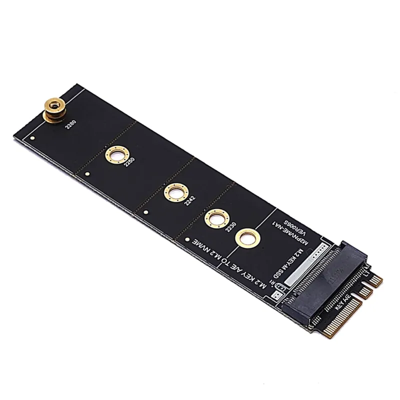
Performance is unaffected, but you should check that you have physical clearance for such an adapter as it extends the card length from 42mm to 53mm. This prevents one from installing the I225-V in the HP T530, as there is insufficient physical clearance for the card with the M.2 A+E adapter.
Finally, the I225-V M.2 designs I have seen are using larger perpendicular headers as compared to the Realtek, meaning they are less likely to fit in small/thin devices like the HP T640 thin client. Given the choice, I would stick to the Realtek for M.2 A+E applications rather than adapting the Intel I225-V.


