Ten years ago, before ARM was in everything, many embedded systems that did not justify using an x86 used PowerPC (or MIPS). This leads us to today’s subject: the Meraki MX80, an “enterprise security appliance.”
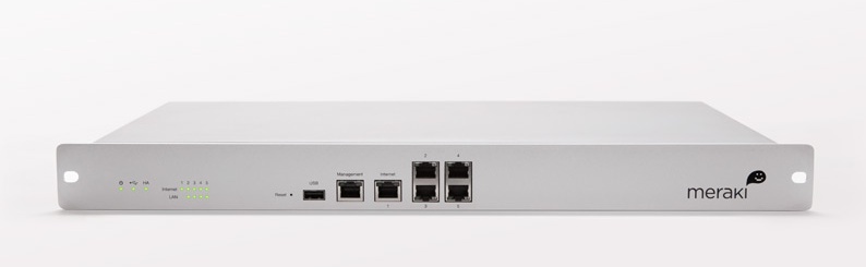
Meraki MX80
The MX80 is End-of-Life (EOL) and can be purchased quite inexpensively on eBay.
The MX-series differs from other Meraki networking products of the 2010-era that we have previously covered (the MS220) in that it is PowerPC based (APM86290) with 2GB of RAM and 1GB of NAND flash. The factory bootlog of the device can be found in this GitHub gist.
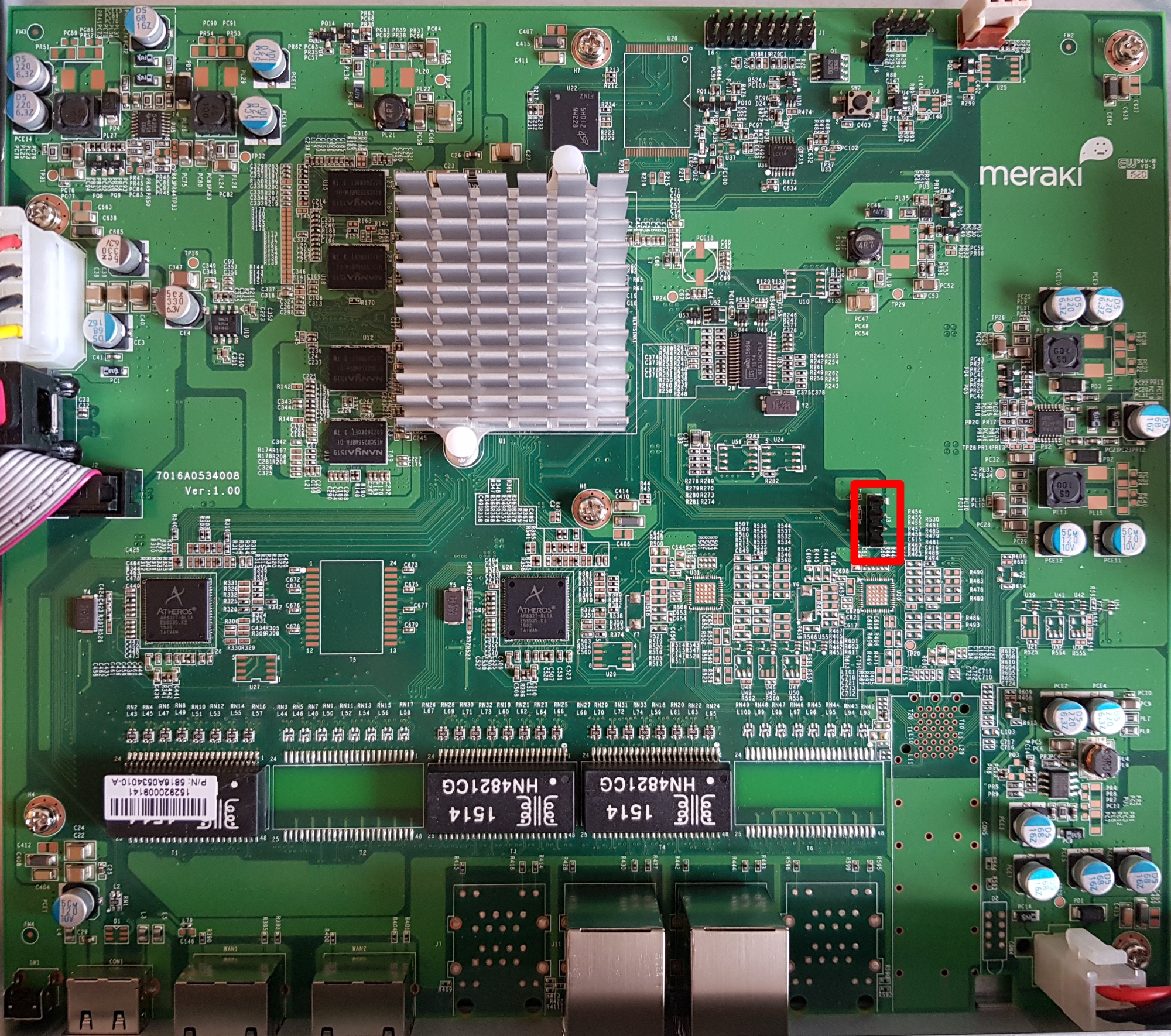
MX80 UART header
J3 (57600n8), with the pinout:
- VCC (don’t connect)
- Rx
- Tx
- GND
Ground (pin 4) is closest to the Ethernet ports.
Obtaining a root shell is very easy as u-boot has a 1 second boot delay and accepts input on UART. The default meraki_boot target sets the bootargs from meraki_bootargs which appends extra_bootargs, so just override rdinit with /bin/sh to prevent the Meraki OS from booting.
setenv extra_bootargs rdinit=/bin/sh
run meraki_boot
Once the MX80 has booted, bring up eth0 (port label Internet on the MX80):
$ mount -t proc proc /proc
$ mount -t sysfs sysfs /sys
$ ifconfig lo up
$ ifconfig eth0 up
$ udhcpc eth0
Once you have functional networking, you can dump the contents of NAND to a remote host for further analysis:
$ cat /proc/mtd
dev:    size   erasesize  name
mtd0: 00100000 00020000 "firmware"
mtd1: 00100000 00020000 "environment"
mtd2: 00040000 00020000 "oops-old"
mtd3: 3fdc0000 00020000 "ubi"
mtd4: 40000000 00020000 "all"
mtd5: 0201d800 0001f800 "part1"
mtd6: 0201d800 0001f800 "part2"
mtd7: 0001f800 0001f800 "board-config"
mtd8: 2001f000 0001f800 "storage"
$ dd if=/dev/mtdblock4 bs=1M | gzip -c | nc -l -p 5000
Running binwalk on “part1” shows us the structure of Meraki’s firmware:
$ binwalk part1.bin

DECIMAL       HEXADECIMAL     DESCRIPTION
--------------------------------------------------------------------------------
1024          0x400           device tree image (dtb)
16384         0x4000          device tree image (dtb)
131072        0x20000         uImage header, header size: 64 bytes, header CRC: 0xD84034B5, created: 2020-05-29 01:15:36, image size: 2447726 bytes, Data Address: 0x0, Entry Point: 0x0, data CRC: 0xCE3A4A5E, OS: Linux, CPU: PowerPC, image type: OS Kernel Image, compression type: gzip, image name: "Linux-3.4.113"
131136        0x20040         gzip compressed data, maximum compression, from Unix, last modified: 1970-01-01 00:00:00 (null date)
4194304       0x400000        uImage header, header size: 64 bytes, header CRC: 0xDA83B155, created: 2020-05-29 01:16:17, image size: 16719915 bytes, Data Address: 0x0, Entry Point: 0x0, data CRC: 0x2381914F, OS: Linux, CPU: PowerPC, image type: RAMDisk Image, compression type: lzma, image name: "Simple Ramdisk Image"
4194368       0x400040        LZMA compressed data, properties: 0x5D, dictionary size: 67108864 bytes, uncompressed size: -1 bytes
There is a device tree image at offset 0x400 which seems to be for the MX60 (codename bluestone). There is a second device tree image at offset 0x4000 for the MX80 (codename fullerene).
It is not as simple as creating a binary image with the DTB at offset 0x4000, the kernel at 0x200000, and initrd at 0x40000 because Meraki have modified u-boot to have a custom command meraki which reads a header, verifies the contents of the ubi partition part1 or part2 with SHA1, and then sets environment variables from addresses defined in the header.
The layout of the header is as follows:
| Header field | Data type (value) |
|---|---|
SHA1_MAGIC |
uint32 (0x8e73ed8a) |
HEADER_LEN |
int32 |
DATA_LEN |
int32 |
SHA1SUM |
char[20] |
MERAKI_EXTRA_MAGIC |
uint32 (0xa1f0beef) |
MERAKI_EXTRA_LEN |
uint16 (0x0006) |
MERAKI_EXTRA_TYPE |
uint16 (0x0001) |
IMAGE_OFFSET |
uint32 (0x20000) |
RAMDISK_OFFSET |
uint32 (0x400000) |
FDT_OFFSETS |
array uint32 (0x400 or 0x4000) |
The FDT used to boot depends on the value of meraki_part_fdt_index in u-boot. For the MX80, the index of the FDT offset is 1, meaning the FDT located at 0x4000 is used to boot. The presence of two FDTs suggests that Meraki are using the same firmware for both the MX60 and MX80. Despite the MX80 being a dual core CPU only one CPU core is usable, there is no SMP support in the kernel provided by Meraki.
To simplify booting, I have written a post-image.sh script which generates the appropriate header and assembles a bootable firmware image as part of the buildroot build process. You can find instructions on how to build the firmware in the meraki-builder GitHub repository.
The 3.4 kernel provided by Meraki doesn’t have any of the features required by OpenWrt (e.g. overlayfs) and buildroot doesn’t have a package manager. If you just want something to boot and run SSH on, then the buildroot image fulfills that need. You will most probably want to customize buildroot to include the packages and configuration that suits your needs. Upstream support in OpenWrt is still a long way away, as the APM86290 does not have support in the mainline kernel.