I know I am late to the “recover your license keys for your Siglent oscilloscope” party, but since I recently went through this to recover my license keys, there is a much easier approach that people don’t seem to be aware of.
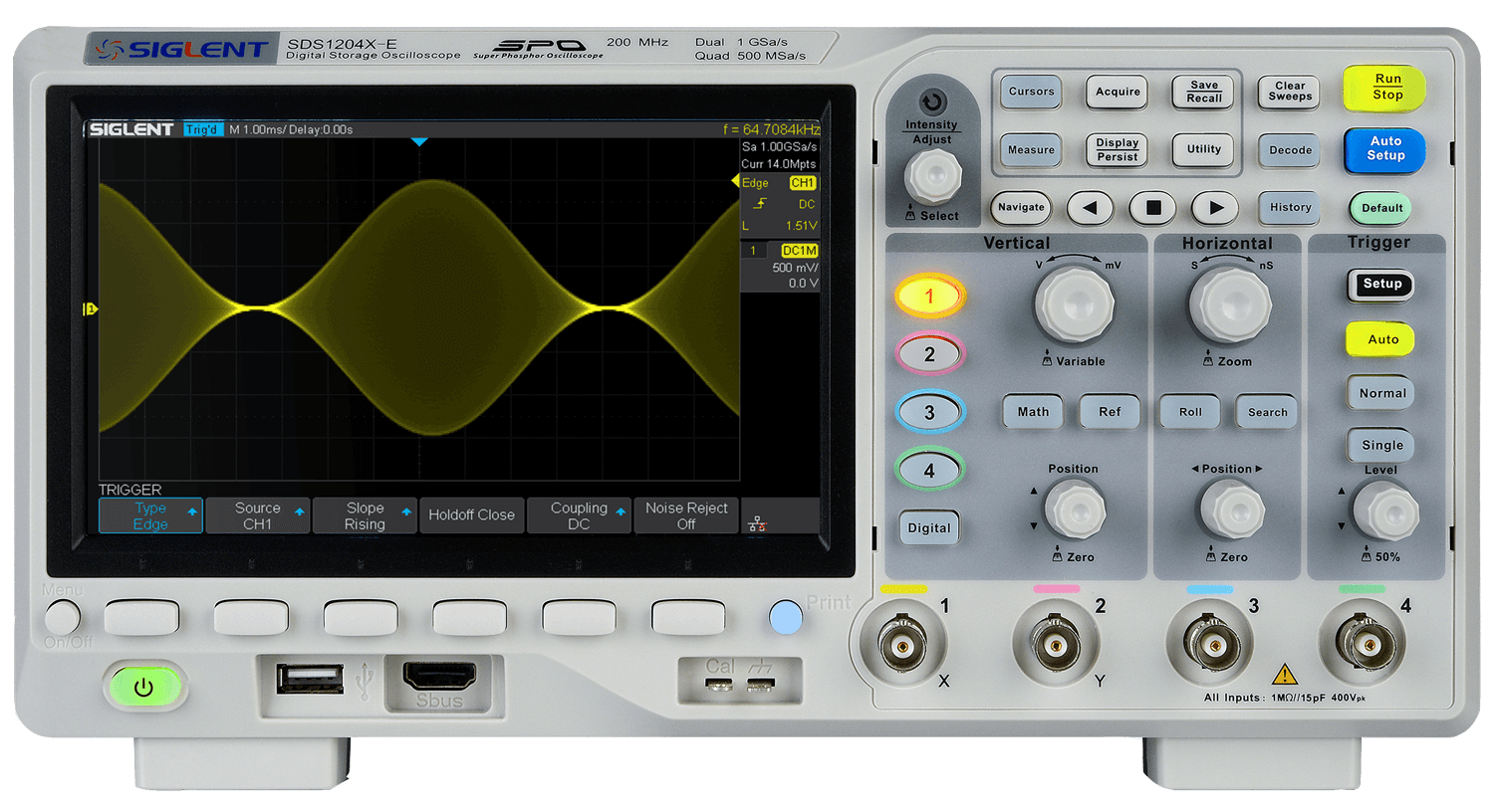
There are several forum topics and blog posts on the subject of recovering license keys for the Siglent SDS1000X-E series.
Most of the methods described involve extracting the cramfs, modifying the password hash of the root user, and flashing the modified image as an update.
There is a much easier way to obtain the bandwidth and option licenses of the scope while using only official Siglent firmware images.
Extract the archive and copy the ADS file SDS1004X_E_6.1.25R2.ADS to a FAT32 formatted USB device
Follow the instructions in the 6.1.25R2 archive to “update” (downgrade) the scope firmware to 6.1.25R2
Navigate to the SCPI control page of the web management interface of the scope
Run the following SCPI command: SHELLCMD telnetd -l/bin/sh -p9999
telnet to the scope’s IP address on port 9999
Dump the memory to the USB device: cat /dev/mem > /usr/bin/siglent/usr/mass_storage/U-disk0/memdump
sync and umount /usr/bin/siglent/usr/mass_storage/U-disk0
On a PC, run this python script with your scope_id, serial, and the path to the memory dump python3 siglent_sds1000xe.py --serial SDSXXXXXXX9999 --sid 012a3456789bc012 --dump /media/usb0/memdump.bin
Install the 200MHz bandwidth license through the SCPI control page using the command MCBD
Install the options licenses SCPI control page using the commands:
LCISL AWG,<code>
LCISL WIFI,<code>
LCISL MSO,<code>
Reboot the scope to apply the changes
After verifying that the bandwidth and option licenses are installed, update the scope firmware to the latest release (6.1.37R8 at the time of writing)
There is no need to repack the cramfs with a new shadow file containing a known root password. Additionally, the license key extraction from memory doesn’t appear to work (or at least, did not provide valid license keys for options on my scope) so I’ve borrowed the contents of a python script from the SDS2000X thread to provide option license keys for the SDS1000X-E. The script is available here.
Note that the 6.1.25R2 firmware has the root passwordsiglent_sds1000x_e. However the password is not required in any of the above steps.
My previous work has mostly involved SPI-based flash, but more modern devices like the Meraki MR33 have only NAND storage and there are instances where it is necessary to modify the contents of NAND using hardware means (e.g. to downgrade u-boot before flashing OpenWrt).
There are a wide variety of hardware NAND flashers available on the market, however they are often expensive, proprietary, and slow. Hardware flashers like a Teensy++ 2.0 running NANDway or the NANDLite (which are both quite inexpensive options) will work for reading data, they are not at all convenient if you want to modify the data and rewrite it. Every NAND chip is unique and has its own bad blocks which you should take into consideration. The net result using these programmers is that you have a very slow workflow: you must obtain a consistent dump of the NAND through a device which often reads at only 100KB/s, modify the contents (recalculating ECC/OOB), and then write it back to the NAND.
Why bother with all of this when Linux has a very robust and fast mtd subsystem in the kernel?
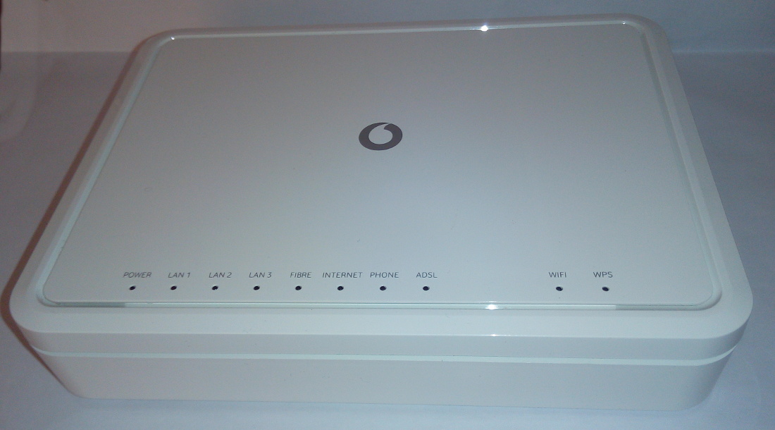
Enter the Sercomm AD1018.
Sercomm AD1018
The Sercomm AD1018 is a DSL router originally produced for Vodafone España and based on the Broadcom BCM6328. There are two hardware revisions, which are the same apart from the amount of RAM: v1 has 64MB of RAM and v2 has 128MB. It can be found on eBay from Spanish sellers for less than 20€, and is supported by OpenWrt. As a bonus, you can easily modify the hardware to add SPI flash and then boot OpenWrt off of SPI.
With the operating system booted from SPI, you have a free NAND interface to do what you want. What do we want? A cheap, Linux-based NAND dumping and flashing platform!
However, there is a problem. The “NOR” OpenWrt image for the AD1018 doesn’t include support in the kernel for BRCMNAND so although there is support in the device tree for the onboard NAND, it is unusable in Linux. This makes the device significantly less useful as a NAND flashing platform.
This is easy to solve though: copy the kernel configuration for the smp target, which includes NAND, to the generic target:
You can download the binary image to flash from here.
After flashing the NOR release of LEDE as described in the installation instructions, simply flash the new NOR image with BRCMNAND support using sysupgrade:
After rebooting you should now be able to access NAND flash from OpenWrt:
[    0.877092] nand: device found, Manufacturer ID: 0x92, Chip ID: 0xf1
[    0.883812] nand: Eon NAND 128MiB 3,3V 8-bit
[    0.888227] nand: 128 MiB, SLC, erase size: 128 KiB, page size: 2048, OOB size: 64
[    0.896083] bcm6368_nand 10000200.nand: detected 128MiB total, 128KiB blocks, 2KiB pages, 16B OOB, 8-bit, Hamming ECC
[    0.908376] Bad block table found at page 65472, version 0x01
[    0.915264] Bad block table found at page 65408, version 0x01
[    0.923011] 1 fixed-partitions partitions found on MTD device brcmnand.0
[    0.930026] Creating 1 MTD partitions on "brcmnand.0":
[    0.935356] 0x000000000000-0x000008000000 : "storage"
Until now, apart from installing the SPI flash, we have only addressed software issues. The kernel output above is the stock NAND which is soldered to the PCB, not exactly practical for flashing NAND from other devices.
The OpenWrt wiki suggests hand soldering a TSOP48 socket to the PCB. I am here to tell you there is a much easier method.
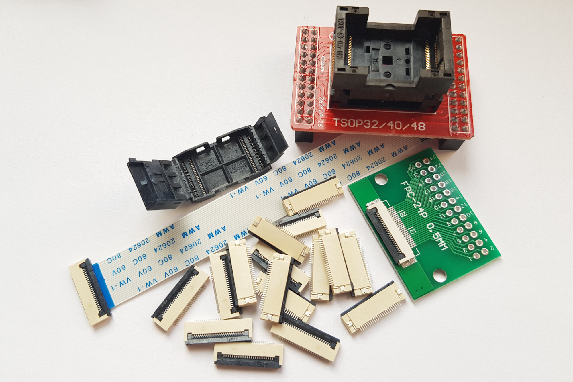
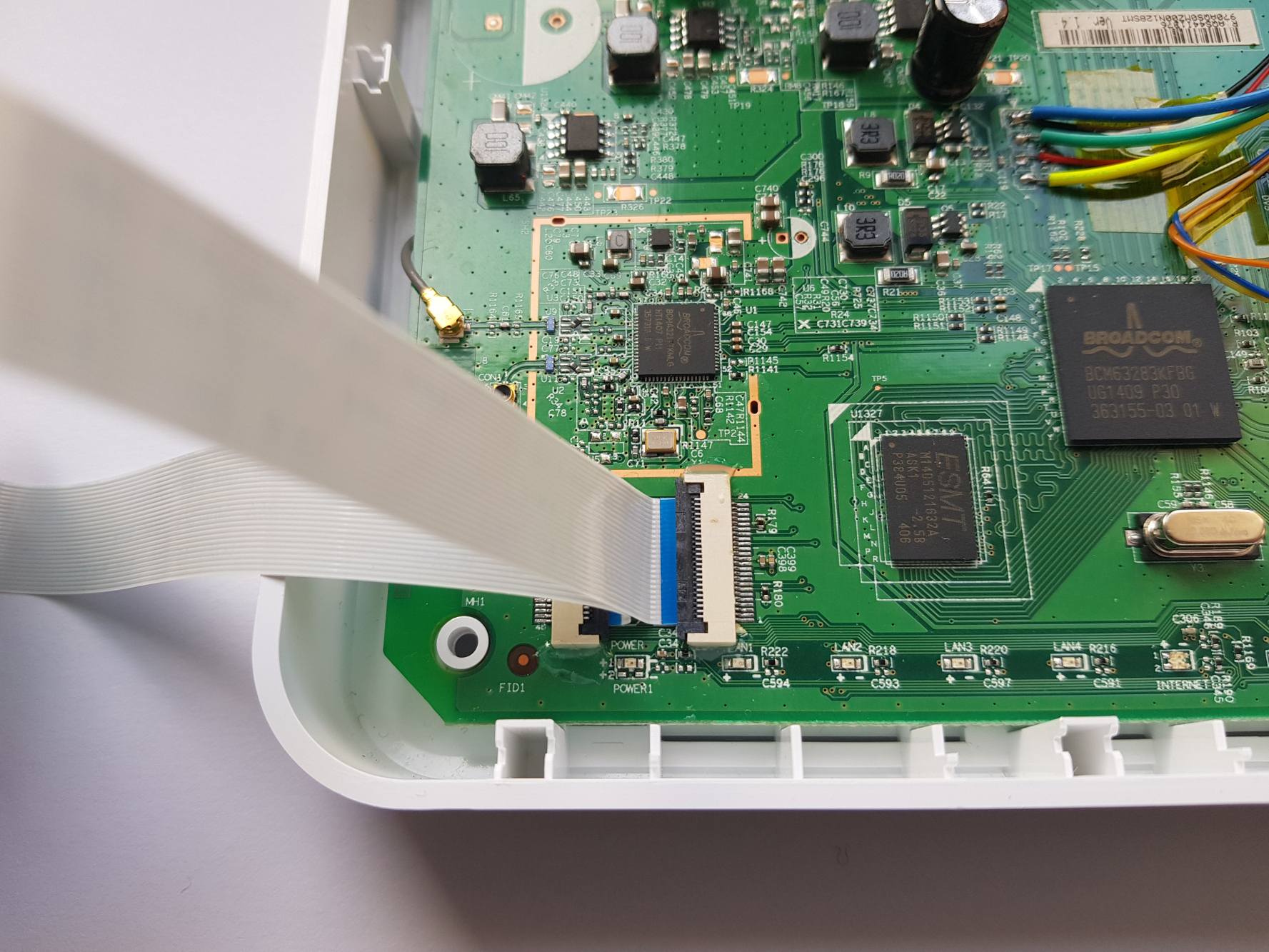
You can purchase TSOP48 sockets for around $5/piece from distributors (or AliExpress) however I dislike these because I still sometimes have difficulties soldering the 0.5mm pitch of TSOP48, and wrecking a TSOP48 socket while soldering gets expensive quickly. In my opinion, there is a cheaper and easier solution: use a 24 pin 0.5mm pitch FPC connector and a TSOP48 socket for a TL866II.
The TL866II TSOP48 socket can be purchased for under $4 on AliExpress. The FPC to 2.54mm breakout PCB, 24 pin FPC cable, and 24 pin 0.5mm FPC connector can all be purchased for dirt cheap (~$0.10/piece) in lots of 10+ from AliExpress. I feel this provides numerous advantages over a surface mounted TSOP48 socket:
FPC connectors are very inexpensive, so if you accidentally destroy it while soldering, no big loss
Since the TL866II TSOP48 socket is connected via FPC cables, you can easily bring it between devices while you are iterating the flash contents
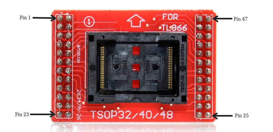
Thankfully, the designers of the TL866II TSOP48 socket routed every pin. However, you should be attentive because the pinout of the TL866II TSOP48 socket is not what you might expect:
When mounting the FPC-24P 0.5mm breakout boards, note that the odd-numbered pins are always on the outer row.
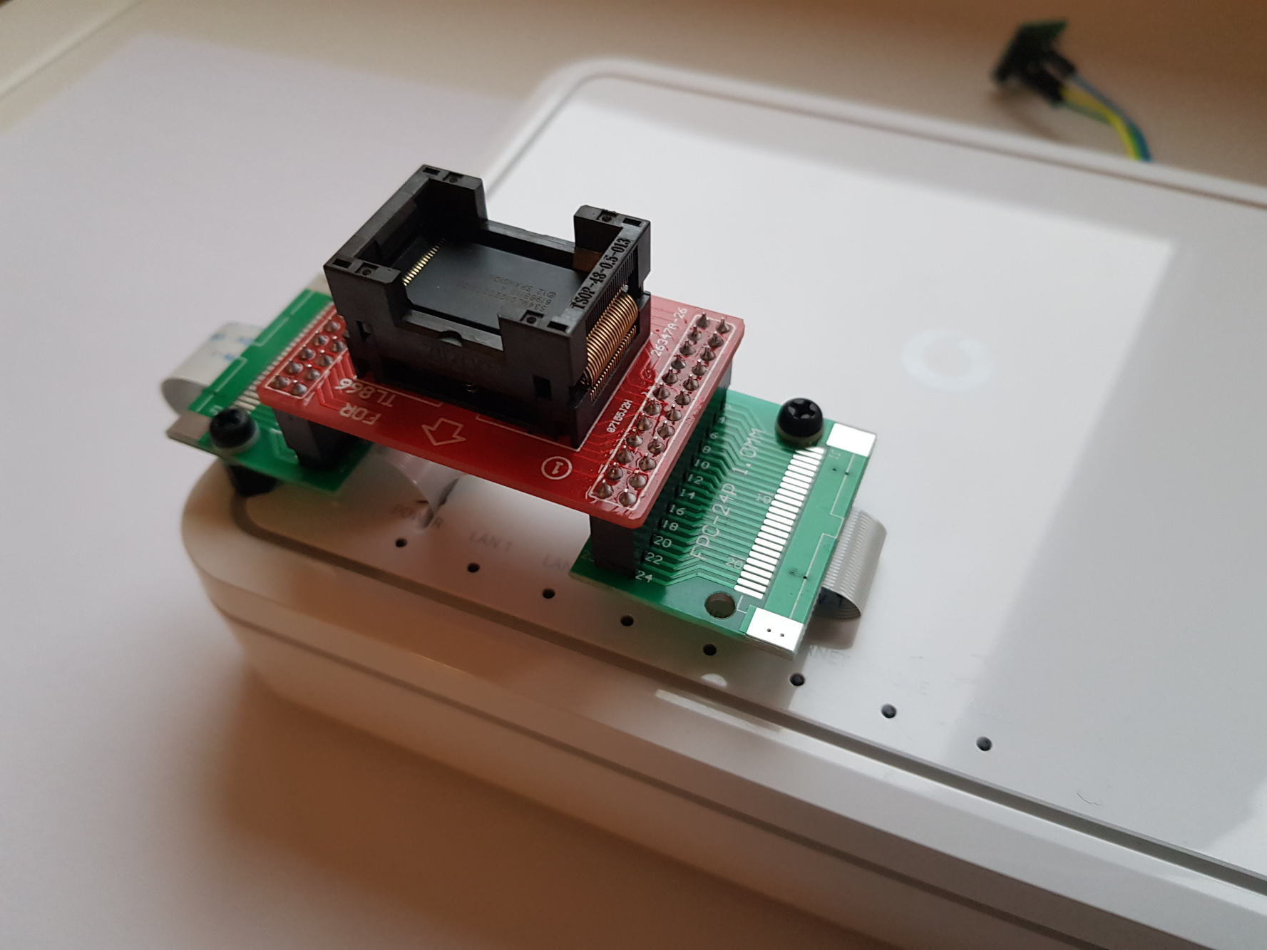
All that remains is to desolder the NAND flash and solder the FPC connectors to the AD1018 PCB
Finally, after cutting a small slot the flat flex cables can be routed outside the enclosure and the TSOP48 socket can be securely mounted
Now it is possible to put the TSOP48 NAND from another device into the socket and use tools like nanddump and dd to manipulate the contents. Since it is OpenWrt, you can even mount a remote filesystem using NFS, sshfs or similar to have even more storage.
While I feel the AD1018 is a very good NAND programmer for the price, there are a few important considerations to consider when comparing the AD1018 against commercial NAND programmers:
You cannot hot-swap NAND (however, it boots quickly and has a physical power switch)
Since brcmnand is built-in to the kernel and not a module, the router won’t boot if NAND is not present
Linux attempts to generate a bad block table when one isn’t present, and this may take quite a long time to complete
The AD1018 is likely difficult to obtain outside Europe
Fujitsu servers come with a remote management solution called iRMC S4 (newer models have iRMC S5). iRMC S4 and S5 are like other lights-out remote management solutions from HP (iLO) or Dell (iDRAC) which comprises a baseband management controller firmware along with other software utilities to remotely configure and manage servers. Importantly though, iRMC S4 runs Linux.
Before we get into the hardware of iRMC S4, let us examine the firmware update process. iRMC S4 follows a pretty typical BMC firmware update process: Fujitsu’s support website offers firmware downloads, and the iRMC web management interface allows you to upload the update which is then written to the inactive firmware slot.
As is common for enterprise hardware, there is no rollback protection, so you can downgrade the installed firmware to previous versions. I did not extensively test this functionality though, so there may be limits to how far you can downgrade as the firmware modifies the persistent conf partition (which is not redundant).
Running binwalk against the update file for the TX140 S2, we can immediately see that it is not encrypted:
These correspond to the lower and higher firmware slots in iRMC S4, and ensure that the firmware you are updating is not the currently running firmware.
So, could our way into iRMC S4 be as easy as modifying the cramfs from the firmware update?
Unfortunately, no. The update is signed and the signature is checked by /usr/local/bin/flasher against an RSA-1024 public key located on the conf partition prior to overwriting:
-----BEGIN PUBLIC KEY-----
MIGfMA0GCSqGSIb3DQEBAQUAA4GNADCBiQKBgQCdgO/cGwthsFEZLuohVB5DNvU/
LolrQobsNASL4Sc+uzn8PsULIPiG0v3zhR8zCwlChmF/umVvk1gxKy5cAY0Bj3oo
cUhXwHf4t2ty+2ZY+p975Yg6YonQJSTKVPVfBlk/9PqNRj/Ih5P3zqd80YxAoKhX
i77qhLxjehHLsRSP2QIDAQAB
-----END PUBLIC KEY-----
Attempting to modify and repack cramfs results in the following output to the UART:
[1533 : 1533 INFO]VerifyImage
Signature Verification Failure
[1533 : 1533 CRITICAL][utils.c:1241]Signature verification failed
[1533 : 1533 CRITICAL][utils.c:1522]Encrypted hash of Image and the actual contents of rom.ima does not match
With our software-only modification route looking grim, it is time to move on into the realm of the evil maid.
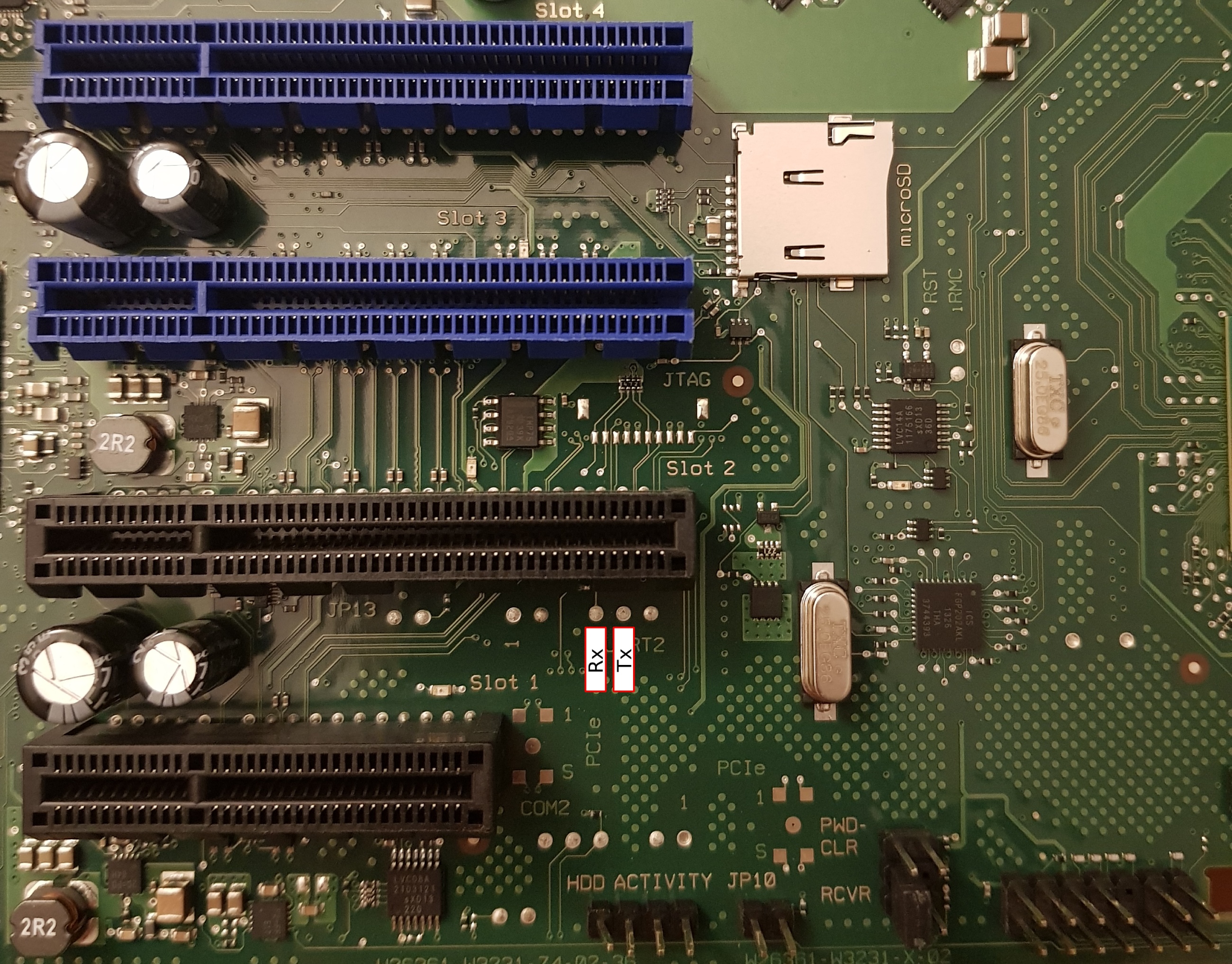
On the TX140 S2 the BMC UART (38400n8) has been routed to pads, located just below PCIe slot 2, which are easily soldered to:
BMC UART on the TX140 S2 (D3239) motherboard
To stop the default boot sequence, press Escape within 2 seconds:
U-Boot 1.1.6 (Jun 20 2013 - 09:09:05)

DRAM:  247 MB
Fast clk is set
Found SPI Chip Macronix MX66L51235F
Flash: 64 MB
Net:   pilot_eth0, pilot_eth1
Hit Esc key to stop autoboot:  0
------ Boot Options-------
        0. Normal Boot
        1. Diagnostics
        2. Remote Recovery
        3. Management Console
        4. Raw Console
Select Boot Option:
The GPL source code for iRMC S4 was requested in December 2020, and at the time of writing Fujitsu had not provided the source code. Without the source code for u-boot, it is difficult to determine if there are any routes that could lead to easy exploitation.
Getting a root console is relatively straightforward with soldering or a chip jig. If you use a jig, you will need very steady hands as flashrom requires 20-30 minutes to write and verify the 27MB cramfs region.
512MBit MXIC flash of the TX140 S2 iRMC S4 BMC
Lucky me, Fujitsu engineers considered physical modification of the iRMC S4 firmware out of scope, and there is no secure boot or signature verification of the cramfs on flash.
Since we can manipulate cramfs, we can bypass the stock Fujitsu shell and replace /usr/local/bin/remman with a symlink to /bin/sh and SSH as the admin user. This is not particularly useful though, as the admin user is not rootsysadmin, and the busybox that Fujitsu ship is lacking the su applet, so there’s no way to easily escalate your privileges from admin to sysadmin once logged in.
~ $ id
uid=1002(admin) gid=501(ipmi) groups=501(ipmi),504(lanoem),510(serialoem),528(iRMCsettings),529(RemoteStorage),530(UserAccounts),531(VideoRedirection),532(CfgConnectionBlade),535(RemoteManager)
The uid 0 account is not called root, but rather sysadmin with the password superuser:
The sysadmin account is not visible in the iRMC web interface and, as far as I can tell, the password cannot be changed (unless you physically modify the contents of cramfs). I believe the account is leftover from the SDK that iRMC S4 appears to be based on.
All my attempts to login as sysadmin via SSH or uart with the default remman shell were unsuccessful, so it doesn’t appear to be a security risk out of the box.
However, once you have replaced /usr/local/bin/remman with a symlink to /bin/sh it is possible to login as the sysadmin user and enjoy root access to your iRMC S4.