Category Archives: Networking

u-boot, boot args, and compressed kernels on the Meraki MS220-8P

The last time we looked at the Cisco Meraki MS220, it was possible to boot kernel 3.18.123 compiled from the Cisco GPL archive. The ability to compile the kernel, with our own command line and modules opened up new possibilities for firmware modification.

That was a very good start, but there is more improvement possible. Support for the Microsemi VCore III SoCs was added to u-boot in late 2018. The MS220-8P contains the Luton26 SoC, but with only 10 ports. The MS220-8P appears to follow the Microsemi PCB090 reference design, and it is possible to build and boot u-boot (v2019.10):

U-Boot 2019.10 (Apr 04 2020 - 09:26:23 +0000)

MSCC VCore-III MIPS 24Kec
Model: Luton26 PCB090 Reference Board
DRAM:  128 MiB
Loading Environment from SPI Flash... SF: Detected mx25l12805d with page size 256 Bytes, erase size 64 KiB, total 16 MiB
OK
In:    serial@10100000
Out:   serial@10100000
Err:   serial@10100000
Net:   Could not get PHY for miim-bus1: addr 0
Could not get PHY for miim-bus1: addr 1
Could not get PHY for miim-bus1: addr 2
Could not get PHY for miim-bus1: addr 3
Could not get PHY for miim-bus1: addr 4
Could not get PHY for miim-bus1: addr 5
Could not get PHY for miim-bus1: addr 6
Could not get PHY for miim-bus1: addr 7
Could not get PHY for miim-bus1: addr 8
Could not get PHY for miim-bus1: addr 9
Could not get PHY for miim-bus1: addr 10
Could not get PHY for miim-bus1: addr 11

Warning: switch@1010000 (eth0) using random MAC address - 62:bf:42:f4:e4:5f
eth0: switch@1010000
Hit any key to stop autoboot:  0 
luton #

u-boot for the Luton26 specifies the environment to be saved at 1MB. This does not match my desired flash layout, so I redefined the ENV_OFFSET and associated variables in board/mscc/luton/Kconfig:

# 64KiB
config ENV_SECT_SIZE
        default 0x10000
# 128KiB at 512KiB
config ENV_SIZE
        default 0x20000
# at 512KiB
config ENV_OFFSET
        default 0x80000 if ENV_IS_IN_SPI_FLASH

Though for some reason this is not working as anticipated, and the environment is still corrupted after saveenv (╯°□°)╯︵ ┻━┻


With u-boot, I was finally able to test booting a compressed kernel. I wonder why Meraki is not compressing the kernel, since compression does not appear to slow down boot at all, and the compressed kernel is much smaller than an uncompressed kernel. Using xz compression, the 3.18.123 kernel is ~2MB, instead of ~5MB. Some fairly trivial modifications were necessary to achieve this.


With u-boot support, testing is much easier. u-boot has network support on the Luton26, making it possible to tftpboot a kernel. This vastly increases the speed of testing as you don’t have to write the kernel to SPI flash before testing changes.

Getting the handoff between u-boot and the kernel for the command line was difficult to figure out. The original bootloader, Redboot, doesn’t have the kernel command line built-in the command line is always compiled into the kernel. In that context, it’s logical why Vitesse didn’t include support for reading the bootloader command line in the kernel (and why Cisco didn’t modify the kernel to include support, since they’re shipping Redboot in these switches).

u-boot was placing the variables somewhere in RAM, but for some reason the kernel wasn’t getting them in its boot command line. u-boot has a humorously titled page on exactly this issue: Linux Kernel Ignores my bootargs. After digging through the u-boot source, it was clear that argv are being passed at the start of DRAM at 0x80000000:

in include/configs/vcoreiii.h: 
#define CONFIG_SYS_SDRAM_BASE           0x80000000
in board/mscc/luton/luton.c:
gd->bd->bi_boot_params = CONFIG_SYS_SDRAM_BASE;

After much searching through the 3.18.123 kernel source code, it became clear that prom is typically where the boot args receiving code is typically placed, so I took inspiration from the lantiq prom code to copy the bootloader argc and argv.

Now, it’s possible to tftpboot compressed kernels with boot args!


Except… there is no serial output from userspace. printk messages are displayed on serial, but no userspace programs (e.g. init) seem able to print out /dev/ttyS0 when using u-boot.

Compiling the kernel with /dev/ttyprintk support and adding custom scripts in /etc/init.d shows that userspace is indeed alive:

[    4.779000] [U] S05printk starting; userspace is alive
[    5.689000] random: dropbear urandom read with 85 bits of entropy available
[    7.356000] [U] Hello from S51printk; userspace is alive but serial is broken

/dev/ttyS0 seems normal, and the memory map is the same as RedBoot (which is logical, since it’s the same kernel version):

[    7.706000] [U] S99 starting; we print stuff
[    7.712000] [U] Now we print /dev
...
[    8.150000] [U] crw-------    1 root     root        4,  64 Jan  1 00:00 ttyS0
[    8.159000] [U] crw-------    1 root     root        5,   3 Jan  1 00:00 ttyprintk
[    8.207000] [U] Now we print /proc/iomem
[    8.222000] [U] 00000000-07feffff : System RAM
[    8.227000] [U]   00000000-00000000 : Crash kernel
[    8.232000] [U]   00100000-0048cc83 : Kernel code
[    8.237000] [U]   0048cc84-0057610f : Kernel data
[    8.241000] [U] 40000000-4fffffff : Serial interface
[    8.247000] [U] 50000000-5fffffff : Parallel interface
[    8.252000] [U]   50000000-50000010 : gen_nand.0
[    8.256000] [U]     50000000-50000010 : gen_nand.0
[    8.261000] [U] 60000000-60ffffff : Switch registers
[    8.266000] [U] 70000000-701fffff : CPU Registers
[    8.271000] [U]   70100000-7010001f : serial
[    8.279000] [U] Now we print /proc/vmallocinfo
[    8.294000] [U] 0xc0000000-0xc1001000 16781312 __ioremap+0x128/0x4ac ioremap
[    8.301000] [U] 0xc1004000-0xc1009000   20480 jffs2_lzo_init+0x18/0x84 pages=4 vmalloc
[    8.309000] [U] 0xc1009000-0xc100c000   12288 jffs2_lzo_init+0x24/0x84 pages=2 vmalloc
[    8.317000] [U] 0xc100c000-0xc100e000    8192 __ioremap+0x128/0x4ac ioremap
[    8.324000] [U] 0xc100e000-0xc1010000    8192 __ioremap+0x128/0x4ac ioremap
[    8.331000] [U] 0xc1010000-0xc1035000  151552 deflate_init+0x44/0xf8 pages=36 vmalloc
[    8.339000] [U] 0xc1035000-0xc1041000   49152 deflate_init+0x98/0xf8 pages=11 vmalloc
[    8.347000] [U] 0xc1041000-0xc1045000   16384 n_tty_open+0x2c/0x14c pages=3 vmalloc
[    8.355000] [U] 0xc1045000-0xc1066000  135168 xz_dec_lzma2_create+0x54/0x9c pages=32 vmalloc
[    8.363000] [U] 0xc1080000-0xc1281000 2101248 __ioremap+0x128/0x4ac ioremap
[    8.370000] [U] 0xc1285000-0xc1289000   16384 n_tty_open+0x2c/0x14c pages=3 vmalloc
[   97.943000] random: nonblocking pool is initialized

I haven’t solved the issue yet of why serial output is broken in userspace 😔
If anyone has experienced broken serial in userspace but not for kernel printk, I’d love to hear how you resolved the problem!

Modifying the Cisco Meraki MS220-8P firmware

Following the analysis done by Leo Leung of the Cisco Meraki MS220-8P boot process, I wanted to share more information I’ve uncovered about the firmware source code, layout, and modification.

Cisco were not very forthcoming with the source code, and initially tried to claim that because the product was past the End of Sale, they were under no obligation to provide the source code. I am not a lawyer, but my understanding is that this claim is in violation of GPLv2 Section 3b, which states the the vendor must make the source code available for at least 3 years after the last distribution:

Accompany it with a written offer, valid for at least three years, to give any third party, for a charge no more than your cost of physically performing source distribution, a complete machine-readable copy of the corresponding source code, to be distributed under the terms of Sections 1 and 2 above on a medium customarily used for software interchange

https://opensource.org/licenses/gpl-2.0.php

I am extremely disappointed to see that Cisco is still not forthcoming with GPL source code. They have little to gain by being so difficult, and it is very disappointing to see them claiming they aren’t under obligation to provide the source code due to the product being discontinued.

To save anyone else the trouble of dragging the source code for Meraki Vitesse based switches (MS22, MS42, MS220, MS320) out of Cisco, I have mirrored the source code into 2 repositories on GitHub:

  • Stage 1 (NOR bootloader, kernel 3.18.122, includes RedBoot LinuxLoader)
  • Stage 2 (NAND firmware, kernel 3.18.123)

Please note: the kernel modules used to control the switch ASIC (vtss_core, merakiclick) are not included in the above source code. If you ever plan to build your own kernel and want to use the switch, you will need to extract the kernel modules corresponding to the above kernel versions from your switch.


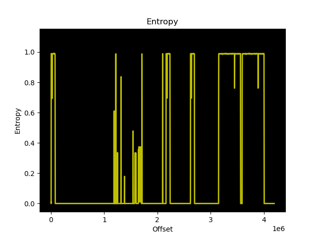
My initial attempts to modify the firmware followed Leo’s instructions to disassemble the mtd region boot1. I was perplexed by the contents of the boot1-patched-post data that Leo’s script extracted from the image. The data in this region has an extremely high entropy:

The data is quite large too, approximately 200KB or 5% of the boot1 region. That’s a lot of space to give up on an embedded system for no apparent reason!

I decided to zero out the contents of this boot1-patched-post section and see what effect it would have on the boot process of the switch. The result was a kernel panic, cannot open initrd:

[    2.537000] devtmpfs: error mounting -2
[    2.541000] Warning: unable to open an initial console.
[    2.548000] VFS: Cannot open root device "(null)" or unknown-block(0,0): error -2
[    2.556000] Please append a correct "root=" boot option; here are the available partitions:
[    2.564000] 1f00          131072 mtdblock0  (driver?)
...
[    2.674000] 1f15            2670 mtdblock21  (driver?)
[    2.679000] mkp_lg: VFS: Unable to mount root fs on unknown-block(0,0)
[    2.679000] Kernel panic - not syncing: VFS: Unable to mount root fs on unknown-block(0,0)

So the kernel can no longer find the initramfs, even though the XZ archive is still present in the region. This got me thinking that the region must contain information the kernel uses to extract the XZ compressed initrd.

The build instructions I received from Meraki with the source code stated:

To build OpenWRT firmware:

cd meraki-firmware/openwrt
cp config-elemental-3.18 .config
make oldconfig
make -j1 BOARD=elemental-3.18 OPENWRT_EXTRA_BOARD_SUFFIX=_3.18


To build Linux-3.18 kernel:

cd meraki-firmware/linux-3.18
cp ../openwrt/target/linux/elemental-3.18/config .config
make CROSS_COMPILE=../openwrt/staging_dir_mipsel_nofpu_3.18/bin/mipsel-linux-musl- ARCH=mips oldconfig

make CROSS_COMPILE=../openwrt/staging_dir_mipsel_nofpu_3.18/bin/mipsel-linux-musl- ARCH=mips prepare

touch rootlist
make CROSS_COMPILE=../openwrt/staging_dir_mipsel_nofpu_3.18/bin/mipsel-linux-musl- ARCH=mips vmlinux

After following these instructions and ending up with a vmlinux that was far too big to fit into the flash region, I figured out how to build the kernel such that it fits into the boot region. This also clarified what the contents of boot1-patched-post from Leo’s extraction script contains.

To start, if you are building the 3.18.122 kernel for the SPI flash (first stage boot, before kexec) you absolutely need a rootlist file. For the stock Meraki firmware, I have re-created the contents of the rootlist file:

file /bootsh ramdisk/bootsh 755 0 0
slink /init bootsh 777 0 0
file /kexec ramdisk/kexec 755 0 0
file /MERAKI_BUILD ramdisk/MERAKI_BUILD 755 0 0
dir /bootroot 755 0 0
dir /dev 755 0 0
slink /lib bootroot/lib 777 0 0
slink /etc/ bootroot/etc 777 0 0
slink /usr bootroot/usr 777 0 0
slink /sbin bootroot/sbin 777 0 0
slink /bin bootroot/bin 777 0 0

The Meraki provided instructions produce an ELF vmlinux, which is not what at all what the switch is booting. You must use objcopy to strip vmlinux before you can get it to what the switch expects in the firmware:

mipsel-linux-musl-objcopy -O binary -S vmlinux vmlinux.bin

By following the above steps, building the kernel with the above rootlist file contents and stripping vmlinux with objcopy, vmlinux.bin is the data that goes into the boot1 region immediately after the 32 byte header. Pad the header + vmlinux.bin with zeros to ensure it is 3932160 bytes total.

Aside: You’re probably not interested in including the same files in your ramdisk as the stock Meraki firmware. Unless you have modified the NAND image to spawn a console and kill their management daemons, you’ll have the same end result as the stock firmware. However, it is a useful test to ensure that you can build and boot the kernel yourself:

Linux version 3.18.122-meraki-elemental (hmartin@alp) (gcc version 5.4.0 (GCC) ) #4 Sun Mar 1 14:44:24 UTC 2020

The meraki_stock branch of the 3.18.122 repository includes the defconfig and rootlist file you need to build the 3.18.122 kernel.


Now onto more useful matters, modifying the bootloader. I grew tired of having CRC errors when testing my changes, so I patched the CRC check out of the bootloader. Later on, I decided I wanted to try booting 3.18.123 directly from NOR, except the stripped vmlinux is nearly 5MB, too large. So I patched out the boundary check in the bootloader. You can find both versions of the bootloader (without CRC and without CRC/boundary check) in the 3.18.122 repository on GitHub.

Meraki appears to supply a common firmware for all their Vitesse based switches. The MS220-8P is based on the luton26 ASIC, while the larger switches (MS22, MS42, MS220-24/48, and MS320-24/48) appear to be based on the Jaguar-1 ASIC. Since you don’t need the kernel modules for other models in the firmware, you can delete them (and other unnecessary Meraki daemons) and fit the entire firmware in roughly 8MB using XZ compressed squashfs.

With this combination, you can boot Linux 3.18.123 from NOR, with a squashfs on NOR:

[    0.000000] Kernel command line:  console=ttyS0,115200 mtdparts=m25p80:0x40000(loader1),0x4c0000(boot1),0x800000(bootubi),0x300000(jffs2) root=/dev/mtdblock3 rootfstype=squashfs ubi.mtd=gen_nand.0 mem=0x7FF0000 ramoops.mem_address=0x7FF0000 ramoops.mem_size=0x10000 ramoops.block_size=0x10000

Since the kernel version matches the modules shipped by Meraki in their firmware, you can load the modules required to manage the ASIC:

# lsmod
vc_click 251569 0 - Live 0xc35eb000 (PO)                                                                                                                                                   
elts_meraki 4132849 1 vc_click, Live 0xc30ab000 (PO)                                                                                                                                       
merakiclick 1587774 2 vc_click,elts_meraki, Live 0xc2854000 (O)                                                                                                                            
proclikefs 5189 2 merakiclick, Live 0xc007b000 (O)                                                                                                                                         
vtss_core 663855 1 vc_click, Live 0xc13f0000 (PO)

This approach is not without its own problems. The Meraki firmware expects / to be mounted rw, something that isn’t possible with squashfs.

In summary, with the following components you can boot directly from NOR, without touching NAND at all:

Please understand that I have not solved all the issues with this approach, and above resources are intended as a guide to encourage future development. To illustrate, here is a flashable image (see here) for your MS220-8P that illustrates booting entirely from NOR. Although I would like to caution you that this is a proof of concept, not a functional firmware. If you have any improvements please submit your pull request the meraki-builder repository!

The above information is the product of months of reverse engineering, development, and testing on an MS220-8P. It is my hope that by providing the GPL archive, my modifications, build scripts, and documentation that others will find a more elegant way to run the firmware entirely from NOR, which would significantly decrease the complexity to running a custom firmware on the MS220-8P.

That’s all for now. I will continue working on this project in the background and may have more updates in the future.

6rd on Free

Today I will discuss how to configure 6rd on the French ISP Free, if you decide not to use the provided Freebox and instead use your own equipment.

Free has been deploying to their customers since 2007. They were one of the first major ISPs to provide customers with IPv6 connectivity. But providing IPv6 for such a long time means they have not always kept up with the latest innovations, and thus Free don’t provide services like DHCPv6 or native IPv6 on some circuits.

If you have FTTH (100/1000MBit), your Freebox will be using the fibre SFP provided during installation. If you instead have xDSL, it will use the included cable to connect directly to the phone line using the DSL port.

With the Freebox, you will have IPv4 and IPv6 connectivity without any effort. But, if you wish to use your equipment after the Freebox you must put it into “bridge” mode and suffer dual NAT. You will also be limited by the features of the Freebox and have to trust Free to keep it updated and safe from vulnerabilities.

Those who choose to use their own equipment must have a device compatible with an SFP adapter, and configure VLAN 836 to receive an IPv4 address via DHCP.

Since IPv6 is provided using IPv6-in-IPv4, further configuration is necessary.

If you are using Mikrotik equipment, detailed documentation exists on how to configure 6rd.

If you are using a Linux-based router (e.g. OpenWrt) the process is slightly different, though the principles remain the same.

Free has an IPv6 prefix of 2a01:e00::/26, with the prefix 2a01:e3a being used for 6rd. The first step to getting working 6rd, is to determine which 6rd gateway Free is using for your IP address. The simplest way to determine this, is to calculate your IPv6 address.

Note: Don’t bother buying a copper SFP and using it in the Freebox to man-in-the-middle the fibre connection with a switch mirror port. It won’t fit physically, and even if you find a way, the Freebox won’t recognize it. ¯\_(ツ)_/¯

Use the prefix 2a01:e3a + your Free IPv4 address in hexadecimal. For example, if your IPv4 address is 8.8.8.8, the first IPv6 subnet would be 2a01:e3a0:8080:8080::/64

Confirm that your IPv6 address calculation is correct by using an online tool to ping the ::1 IP address in this IPv6 subnet, while running tcpdump on your router and filtering for protocol 41. If you have calculated the IPv6 address correctly, you should see IPv4 encapsulated IPv6 packets reaching your router:

# tcpdump -i eth0.836 proto 41
07:29:54.229910 IP 192.88.99.101 > lns-bzn-30-XX-XX-XX-XXX.adsl.proxad.net: IP6 2600:3c01::f03c:91ff:fe93:48f8 > 2a01:e3A:ABBB:CCC1::1: ICMP6, echo request, seq 1, length 64

At this point, since we have not configured the 6rd tunnel, you should not expect to see any echo replies from the IPv6 address. Note the source IP address of the packet, this is the 6rd gateway from Free.

Before continuing, you need to add a firewall rule to allow protocol 41 through your firewall to the IP address of the Free 6rd gateway. From the above tcpdump output, the rules to add would be:

iptables -I zone_wan_input -i eth0 -p 41 -s 192.88.99.101 -j ACCEPT
iptables -I zone_wan_output -o eth0 -p 41 -d 192.88.99.101 -j ACCEPT

OpenWrt does include support for 6rd in Luci, but I was never able to have this configuration bring up a working 6rd tunnel. Instead I configured the tunnel manually in /etc/rc.local:

ip tunnel add 6rd mode sit remote 192.88.99.101 local 170.187.188.204
ip link set 6rd up
ip addr add 2a01:0e3A:ABBB:CCC0::1/64 dev 6rd
ip addr add 2a01:0e3A:ABBB:CCC1::1/64 dev br-lan
ip route add ::/0 dev 6rd

This is almost enough to have IPv6 connectivity working fully. However, your IPv6 routing will be broken, as this interface is manually created and doesn’t belong to the LAN or WAN zones.

To resolve this, go to the OpenWrt web GUI and create a new interface with the Unmanaged protocol, covering the 6rd interface. Assign the new interface to the WAN zone, and restart the firewall. IPv6 routing should now be functional.

You should also configure the LAN interface to have the Router Advertisement-Service and DHCPv6 Service in server mode. This will ensure clients receive an IPv6 address in the IPv6 subnet assigned to the LAN.

I recommend rebooting your OpenWrt router to ensure that your configuration is correctly applied on boot.

You can check that IPv6 is correctly configured correctly by using an online tool such as test-ipv6. If everything has been configured correctly, your test results should be positive!