Tag Archives: UEFI

Reassembling a firmware from pieces

Working on firmware is always interesting. Modern x86 computers are incredibly complicated, due to the evolution of the architecture over the last 40 years, and it’s difficult to debug issues past “Well it doesn’t POST, better try something else.”

Unlike most ARM/MIPS systems, where you have a UART console or something to see output from u-boot, if you mess up the firmware on an x86, you’ll have a non-communicative brick on your hands.

Of course you can also have firmware issues on ARM/MIPS, if you manage to corrupt u-boot on SPI flash, but since u-boot is open and not proprietary it’s easy to rebuild it from source and flash it again to recover.

Not so in the PC world. UEFI is horrendously complex compared to u-boot, and Intel’s reference implementation known as TianoCore is usually “improved” by several middlemen before going into the final product.

Trammel Hudson’s excellent talk from 33c3 (slides) on Bootstrapping a slightly more secure laptop highlights the situation with UEFI quite well:

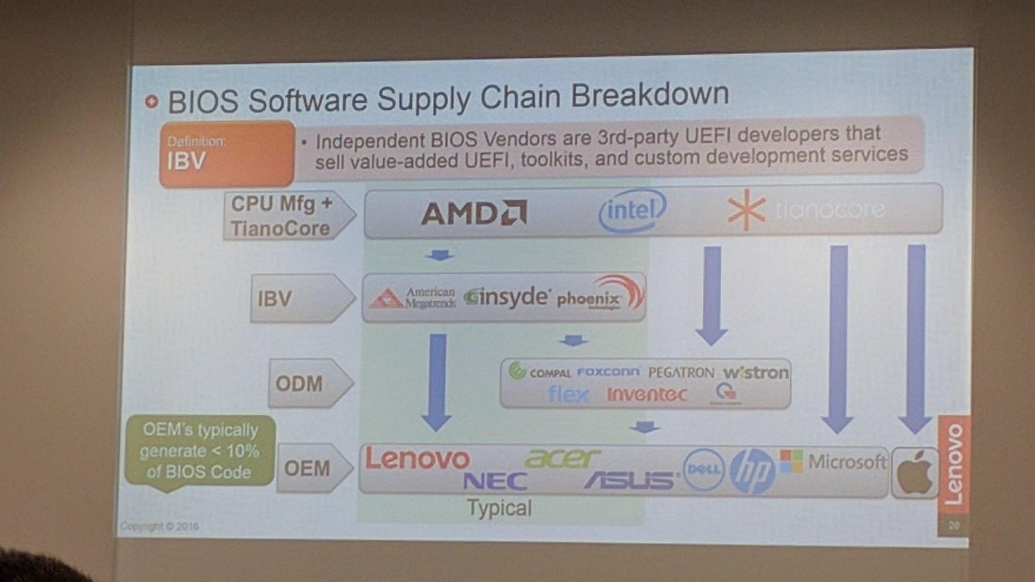
Farm to table firmware

In this case, we’ve got TianoCore from Intel, insyde adds some magic fairy dust, this goes to Compal (the ODM of this laptop), and finally Dell (who would probably also claim to add magic fairy dust). In the end there’s a lot of proprietary fairy dust floating around, and we probably wouldn’t be able to boot the laptop if we just build TianoCore from source.

TianoCore itself is open source and BSD licensed, which is why all the vendors use it. Intel manages porting TianoCore to their new platforms, and since it’s BSD licensed, it means that someone like insyde can take the working base from Intel and add their proprietary fairy dust without having to release the modified source code.

SPI flash
The start of flash contains a region called the Flash Descriptor (PDF; page 3) which is programmed at system manufacture and tells the system where different firmware components are present on flash. Think of it as a partition table for the system flash. Under normal circumstances, the flash descriptor prevents the user from reading and/or writing portions of ROM. If you try to use tools to read or write the ME regions of flash, you’ll get a error similar to this:

Error 26: The host CPU does not have read access to the target flash area. To en
able read access for this operation you must modify the descriptor settings to g
ive host access to this region.

And this makes sense. If the system allowed unrestricted write access it would be trivial for some malware to write itself into the system firmware, and then you’d have a persistent rootkit. In my opinion, blocking the ability to read portions of the firmware serves no purpose except to discourage reverse engineering attempts.

Thankfully, there is a method known as Flash Descriptor Security Override Strap which can be used to disable the flash descriptor protection.

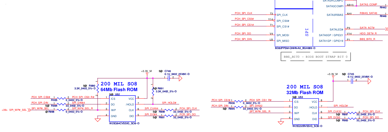
The first step is to locate the ME_FWP pin in the circuit diagram:
Override Strap

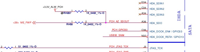
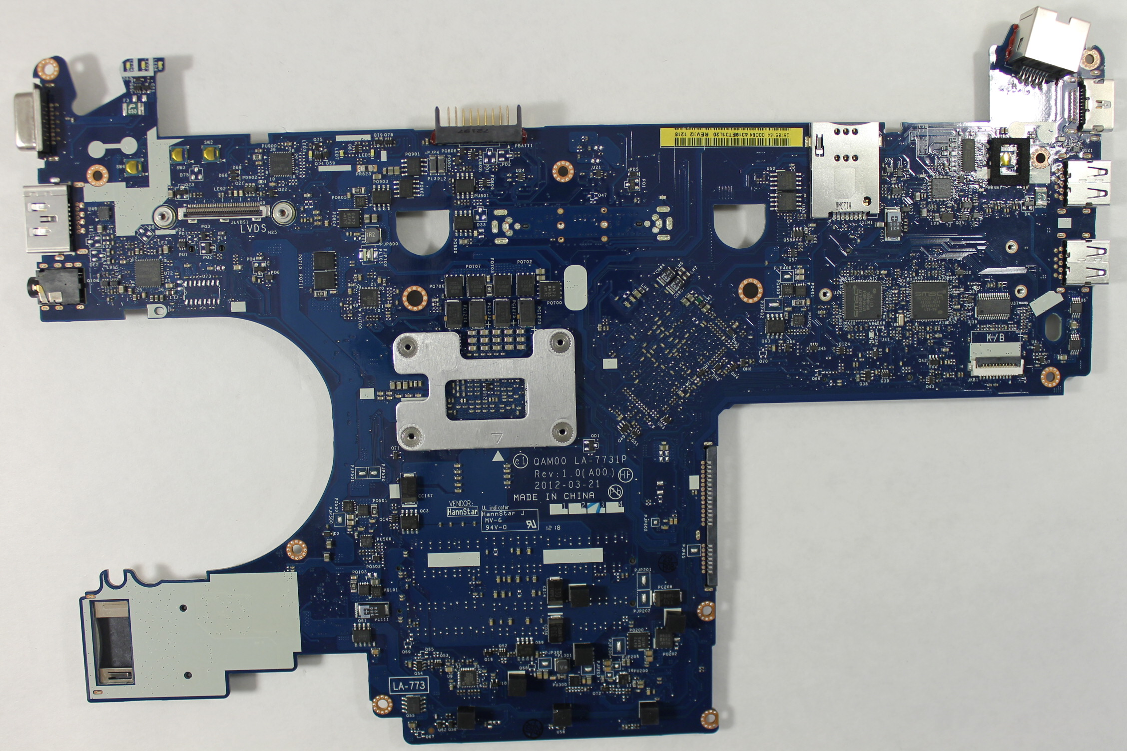
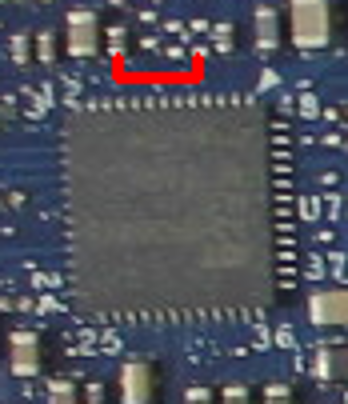
Now that we’ve located the pin on the logical diagram, we need to find the HDA chip itself so we can see which pins we need to bridge to disable the flash descriptor lock on the ME region:
la-7731p_sda

In this case, it’s most convenient for us to short pins 5 and 9:
la-7731p_hda

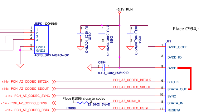
You could also short pins 1 and 5, but this requires a very steady hand and small instrument. However pins 5 and 9 are connected to surface mount components located away from the chip. These components (a capacitor and a pad) are much easier to access with a wire:
la_7731p_pin5_pin9

Amazingly, this area can be accessed without completely disassembling the laptop. Just taking off the palm rest and keyboard, which is about 8 screws, is enough to access the pins. They’re right under the LVDS cable to the display. Thanks, Compal!

At this point, I have two options:

  1. Find or buy an SPI dump online and flash that
  2. Find a way to dump the firmware from the working laptop without soldering

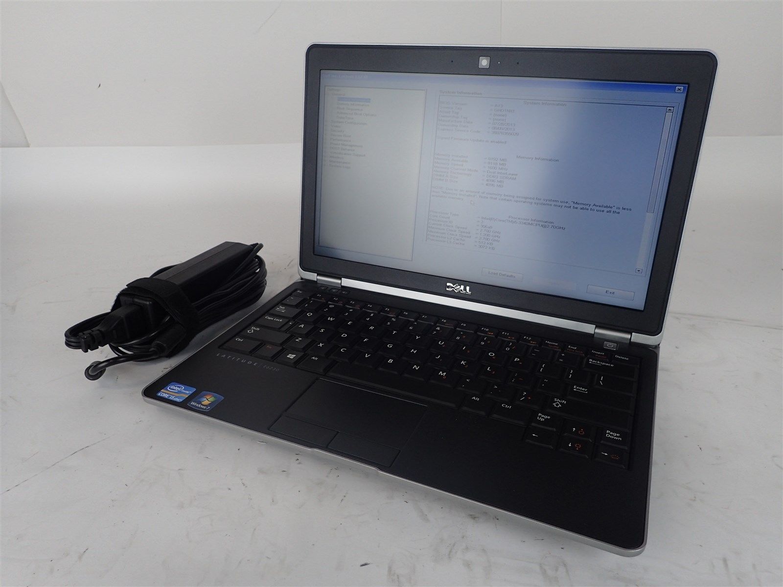
As you read in the previous post, I only managed to find an E6320 SPI dump online, and ended up with a laptop that worked-ish. I tried for many hours, but I wasn’t able to find any free SPI dumps for the E6230 online. After seeing many forums promising to sell you the firmware for outrageous prices, I finally found one that wanted only 8 złoty ($2) to download the SPI dump for the E6230. Principles be damned, I’ve wasted enough time trying to get this to work. I paid up and downloaded the files for the 4MB and 8MB chips.

Did I really get a valid firmware for $2? Yes!

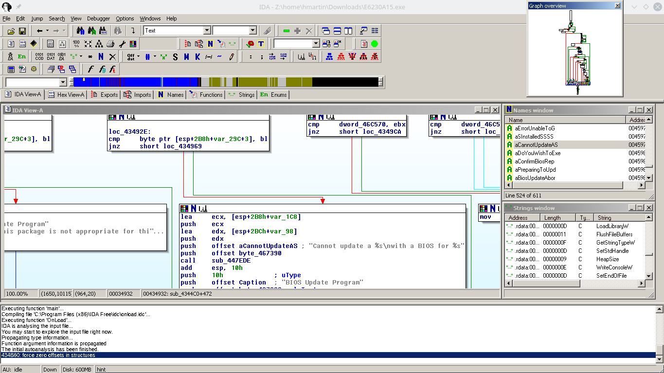
But it’s BIOS A12, the current version is A16, but none of the Dell update utilities work! I installed Windows to try the update tool from Dell, but the laptop just rebooted without updating the firmware. I tried from FreeDOS and again, the laptop would just reboot when it got to flashing. Hrmm…

So, at this point I’m going to cheat a little: I have a working E6230, but I decided when I started this that I would not touch it with a soldering iron or heat gun. If it ain’t broke, don’t fix it!

Can I get a full firmware dump from the working E6230?

Intel FPT

Intel FPT is a proprietary command-line utility created by Intel for flashing firmware files through the computer’s internal SPI flashing interface.

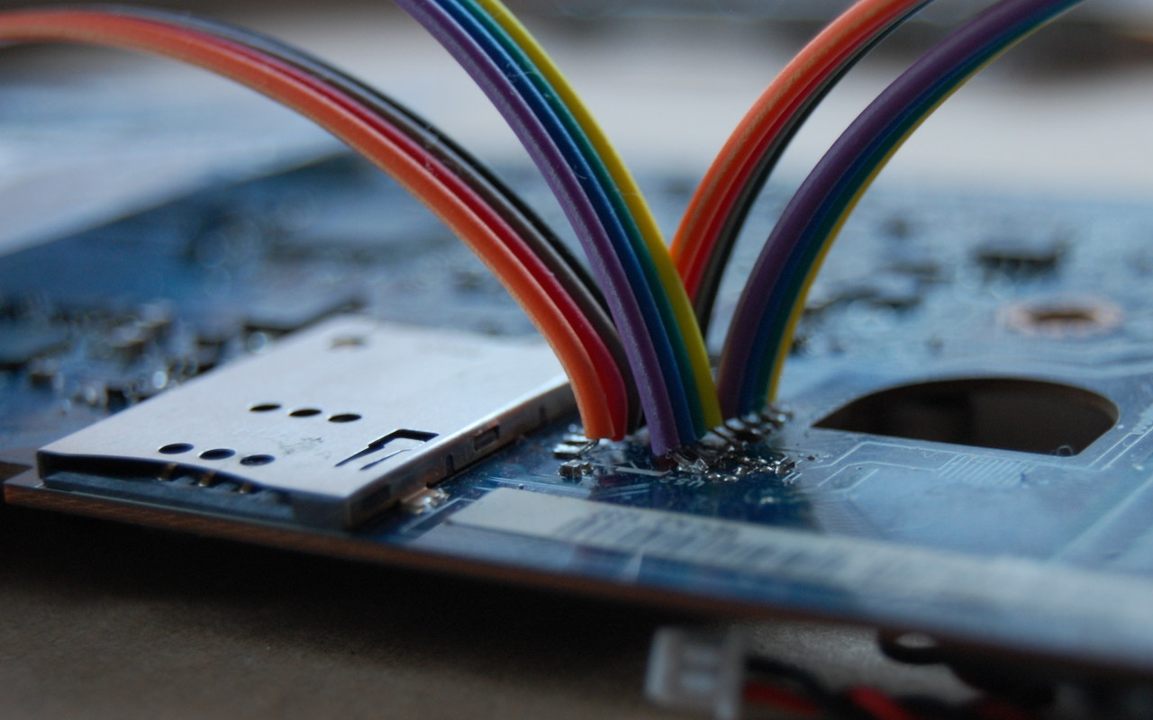
Alright, let’s go dump the firmware! First you need to remember to apply the Flash Descriptor Security Override Strap, or the CPU will block your read attempt to the ME region.

However, once we’ve done that, FPT will allow us to dump regions of flash to a file.

At first I tried to dump just the ME and BIOS, using the A12 firmware from above, I reflashed these regions using the FPT utility from FreeDOS. The verification of the BIOS region failed, and when I rebooted I had a brick again.

But, the FPT tool lets you dump all the regions at once! I dumped the entire flash, but now we’ve got a 12MB file and I don’t know where the split is between the 8MB and 4MB flash chips.

After more searching, I found the Intel ME System Tools, including a utility called Flash Image Tool, which allows you to import the firmware image file created by FPT.

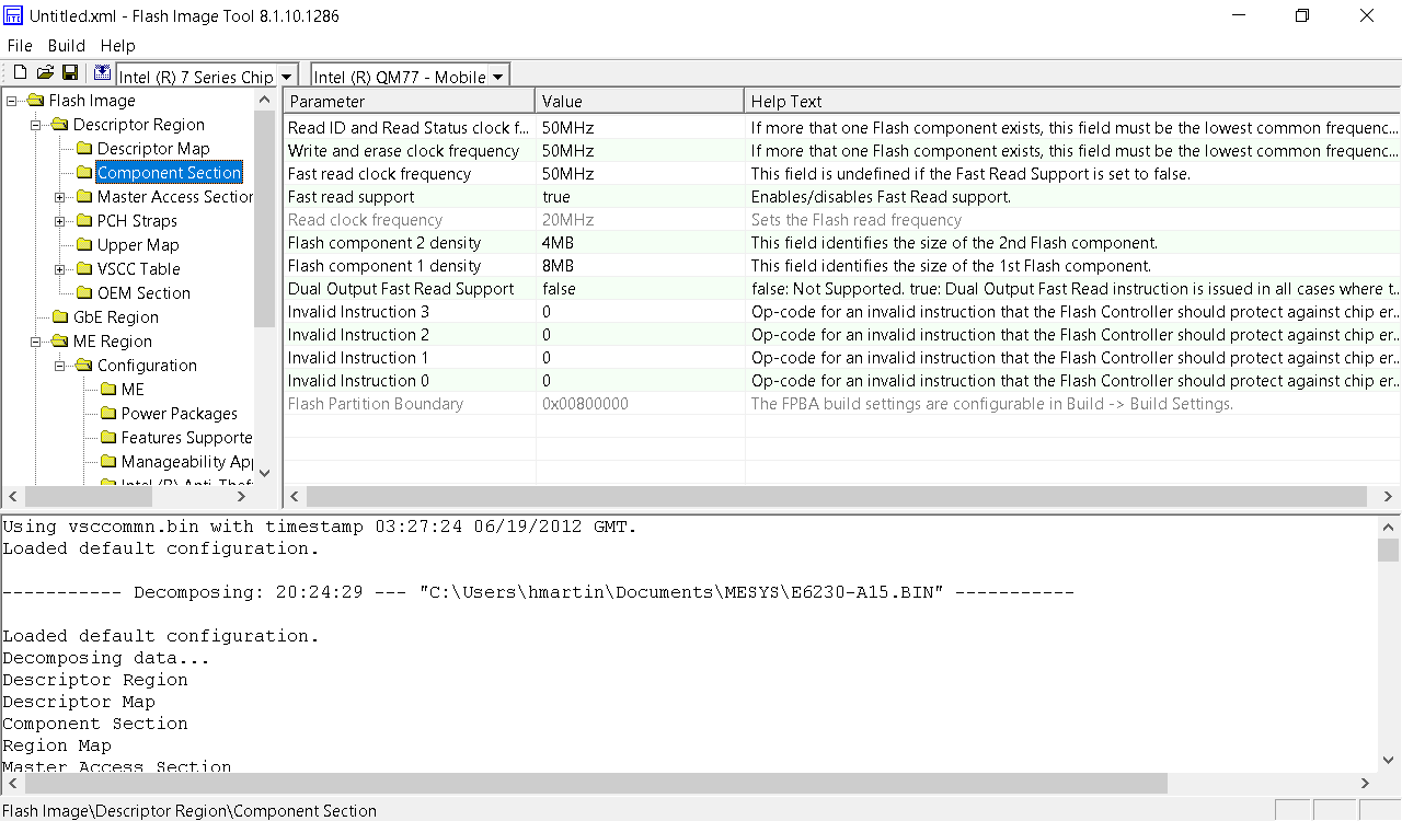
Well, the flash component density matches what’s in the laptop, so I guess this is correct.

Flash Image Tool also lets you build a new firmware image:

Writing ROM image file “C:\Users\hmartin\Documents\MESYS\Flash Image Tool\v8.1.10.1286\Build\outimage.bin”.
Writing file “C:\Users\hmartin\Documents\MESYS\Flash Image Tool\v8.1.10.1286\Build\outimage(1).bin” (size = 8388608)
Writing file “C:\Users\hmartin\Documents\MESYS\Flash Image Tool\v8.1.10.1286\Build\outimage(2).bin” (size = 4194304)
Writing MAP file “C:\Users\hmartin\Documents\MESYS\Flash Image Tool\v8.1.10.1286\Build\outimage.map”.

Image size = 0xC00000 bytes

Interesting… outimage(1).bin is exactly 8192KB, and outimage(2).bin is exactly 4096KB. I wrote these two images to the respective chips and put them into the laptop. The moment of truth had arrived.

It boots!

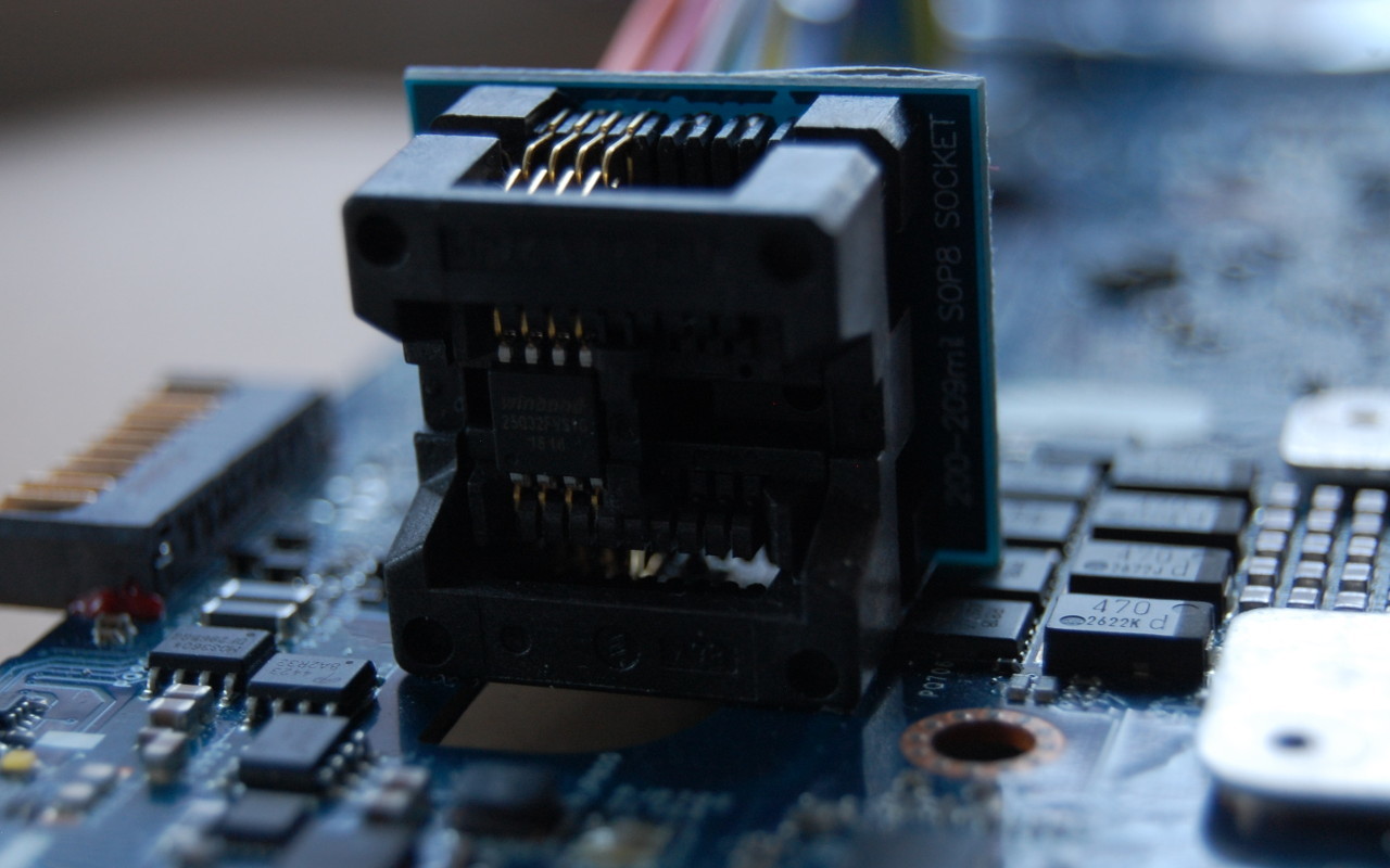
When you’re trying to work through firmware issues, it’s really helpful to have the flash chip in a socket. Soldering and desoldering gets really old when you have to do it more than a couple of times.

Thoughts on the sale of firmware images

I’m against the sale of these firmware images. I realize that it takes a non-zero amount of time to get the image, but the whole experience of BIOS forums just leaves you feeling dirty. You have no way to verify before payment that the files they’re providing even work. Combine this with the fact that most websites want $10-$20 for the SPI dump, the experience leaves a bad taste in your mouth.

Is it worth it to pay? It depends entirely on your willingness to pay. Is this your only computer? Do you need it working now? How much of your own time are you willing to invest to learn about UEFI firmware? I’ve probably put 20 hours into this project, and I still don’t understand the internals of UEFI.

The wrong way to clear a BIOS password

I was browsing on eBay and ran into a listing for a Dell E6230. By now you might guess where this is leading:

Dell Latitude E6230 12.5″ i3-2350M 2.3GHz 4GB RAM Admin Pass Set AS IS READ!

s-l1600

The whole laptop, everything working perfectly, except… it has a firmware password set, and the seller doesn’t know the password. Well no bother, it’s cheap (83 EUR), I know how to flash SPI chips. Should be a piece of cake to clear this password! I also had an E6230 motherboard with a Core i5-3320M which I had found on eBay for 40 EUR, so my plan was to swap the boards, and then work on clearing the password.

These boards contain two flash chips: Winbond 64Mbit (8MB, U52) and Winbond 32Mbit (4MB, U53) located to the left of the SIM card slot.

f_0020914

The first step was to dump the SPI flash from U52 and U53 on both boards as a backup before flashing anything. This seemingly went well, but when I flashed the i5-3320M firmware dumps to the board with the i3-2350M, I had a brick.

It turns out that several of the pins to each chip are connected to the same pins in the PCH. Important pins like Data Out, Clock, and Data In are shared:

PCH SPI wiring

U52 and U53 share data out, data in, and clock lines to the PCH


I’m not sure exactly what happened, but my guess is that by leaving the flash soldered to the board, I somehow managed to get data from both chips. Alarms should have been going off in my head when my SPI reader dumped 8MB from a 4MB chip.

Not wanting to risk wrecking the i5-3320M board by desoldering the flash, I turned to the internet and discovered the terrible world of BIOS image dumps. It’s nearly impossible to find any website offering SPI dumps for free. Of course you can download the firmware update tool from the manufacturer, but those are meant to be run only on the intended hardware, and they only contain regions of the SPI flash like the UEFI firmware and Intel Management Engine.

I was able to find an SPI dump of the E6320, which is a 13.3″ laptop one generation previous to the E6230 (12.5″). As I had nothing to lose, I desoldered U52 and U53 and flashed the E6320 images to each chip. To my great surprise, the board passed POST, albeit with a warning about unsupported hardware. I was even able to enter the UEFI setup utility.

But now I am running a firmware intended for a completely different laptop. The E6320 has a QM67 (6 series) chipset, and the E6320 has a QM77 (7 series) chipset. The USB 3 ports on the side don’t work, the internal SATA port doesn’t work, and PXE booting doesn’t work. The only port that seems to work, at all, is a Mini PCIe USB port:

mini_pcie-usb30-1_zps098e038b

My next thought was to try the Dell E6230 BIOS update tool, which can run from DOS. I put FreeDOS on a USB stick in the above adapter and installed that in the WWAN Mini PCIe slot. Unfortunately for me, Dell has put checks into the update utility to check that it’s running on the correct hardware. This makes total sense, if a user downloads the wrong update for their laptop, they shouldn’t end up with a brick.

However, it didn’t suit my purpose. I wanted Dell’s BIOS update utility to ignore the fact that it was running on an “E6320” and instead flash the firmware for the E6230, the actual hardware.

Having been foiled by Dell’s checks, I decided to load up the utility in IDA Pro to see if I could bypass the check. A bit of string searching and I found the target, a jnz:
ida_jnz

Changing this check to a jz and I tried again. This time the utility didn’t complain about the machine being an E6320, but as soon as the flashing process started, the laptop shut off. So what happened? My best guess is that Management Engine shut down the platform.

Management Engine
The Intel ME has existed since the mid-2000’s, and is now deeply integrated into all of Intel’s modern x86 SKUs. The ME can provide additional functionality like a TPM (implemented in firmware), cryptographic acceleration, DRM, as well as other patented and super duper proprietary stuff. There’s a fairly comprehensive feature list available on Wikipedia.

Since Intel doesn’t actually release documents on the ME, it’s hard to come by actual information on the inner workings. It’s also why some libre people are concerned about buying newer laptops: the ME is integrated into the PCH, cannot be disabled, runs an OS with direct memory access to system RAM and has never been audited.

Trammell Hudson is currently experimenting with coreboot on the Lenovo X230, and it seems like there’s a non-zero chance that he’ll succeed in disabling the ME.

Anyway, I was on vacation earlier this year and had lots of time to kill in airports/planes/trains so I read a book about the Intel ME called “Platform Embedded Security Technology Revealed” You can download the ebook for free as a PDF or EPUB from the publisher.

Using knowledge from the above book, we can conclude that the security number of the Series 8 ME firmware must be equal to the security number of Series 7 firmware, or the ME would not allow the platform to power on.

Unfortunately, the updater managed to overwrite something important in flash before the ME cut power, because now I’m stuck with a brick again.

Stay tuned for part 2!

CompuLab MintBox 2 Review

Update 11 December 2017: If you own a MintBox 2 or Intense PC and would like to run an open-source firmware which is not vulnerable to CVE-2017-8083 or CVE-2017-9457, consider flashing coreboot.

Update 30 July 2017: If you own a MintBox 2 or Intense PC your system is vulnerable to CVE-2017-9457. There is currently no planned fix for this vulnerability.

Update 6 June 2017: If you own a MintBox 2 or Intense PC, please update your system firmware to the latest version (21 May 2017). Your system is vulnerable to CVE-2017-8083.

CompuLab’s MintBox 2 is a small embedded computer designed for home, office or industrial applications that retails for $599 US. The MintBox 2 ships with Linux Mint 15 “Olivia” on it, which was supported until January 2014 (last month).

The specifications of the MintBox 2 are:
Intel Core i5 3337U (Dual-core 1.8GHz, 2.7GHz turbo, 17W)
4GB RAM (2x2GB; DDR3 1333 CL9 SODIMMs)
500GB hard drive (2.5″, 5400RPM, Hitachi HCC547550A9E380)
Dual Gigabit Ethernet (Intel and Realtek 8111F; both integrated)
Realtek 802.11b/g/n 2.4GHz WiFi/Bluetooth 3.0 combo card (RTL8723AE; half-height mini-PCIe)

Also present are two eSATA ports (SATA 300), a full size mini-PCIe which can also double as mSATA, DisplayPort and HDMI (CEC is not supported) video outputs, and 3.5mm audio in/out which also support S/PDIF (coax).

The MintBox 2 comes with a 60 month warranty (5 years), with the hard drive being covered for 24 months (2 years).

The shipping configuration uses legacy booting and partitions instead of EFI booting and LVM.

Disk /dev/sda: 465.8 GiB, 500107862016 bytes, 976773168 sectors
Units: sectors of 1 * 512 = 512 bytes
Sector size (logical/physical): 512 bytes / 4096 bytes
I/O size (minimum/optimal): 4096 bytes / 4096 bytes
Disklabel type: dos
Disk identifier: 0x16ad26de

Device Boot Start End Blocks Id System
/dev/sda1 * 2048 968752047 484375000 83 Linux
/dev/sda2 968752048 976773167 4010560 82 Linux swap / Solaris

Encrypting user’s home is supported and offers reasonable speeds, but since user data is stored on the same partition as the OS you may run into trouble if you try to upgrade Linux Mint or install another distribution.

The MintBox 2 supposedly supports up to 16GB of memory, and indeed I had no issues with the 4GB installed, or with an 8GB (2x4GB) kit from Patriot memory. I tried three different 16GB kits (G.SKILL, Patriot, Micron) in the MintBox 2, and all three were incompatible. As such, I highly recommend you consult the list of approved memory modules before purchasing a 16GB kit for the MintBox 2. I am awaiting a 16GB kit that was certified to work with the MintBox 2 and will update this post when it arrives.

People familiar with Linux Mint will know what the standard user interface is like, and the MintBox 2 does not deviate from it apart from a cheeky MintBox 2 wallpaper. Everything works out of the box, with ethernet and wireless configured for DHCP. Suspend to RAM works well and performance is on par with other dual-core computers running Linux Mint.

I installed Arch Linux on my MintBox 2 using EFI boot. This requires reformatting the hard drive completely to use a GPT partitioning scheme. An EFI service partition is required to store the grub boot loader, unless you opt to use the EFI stub in the linux kernel (which I did not). You will also have to boot from live media and use the efibootmgr tool to insert a boot record into EFI nvram to point to your boot loader or you will be sitting sadly in the [seemingly] useless EFI shell wondering why it won’t boot.

As with most other consumer electronics, there is little to no option to tweak in the EFI configuration utility (“BIOS”). There are no voltage monitors, and only the CPU temperature sensor is available over SMBus. Users do not have control over CPU speed, C-states, memory frequency or timings. There is an option for whether the full-height mini-PCIe slot is mSATA or regular mini-PCIe, and users can choose to enable or disable Virtualization (VT-x; VT-d is not supported by the HM76 chipset).

The December 2013 firmware update provides users with the ability to pre-define how much memory to share with the IGP (128MB, 256MB or 512MB) which is reserved and unavailable to the OS. I believe previous firmware versions dynamically allocate VRAM based on the Intel IGP driver requests from the OS.

Depending on the workload the CPU temperature can vary from mid-40s to mid-70s (Celsius), but is almost never hotter. This is average for a mobile CPU and well within safe limits. The stock RAM hits mid-60s in heavy use, but DIMMs with 16 chips (as opposed to 8) run in the mid-70s.

CompuLab support was a little lacklustre at first, but improved tremendously after I discussed my issues with the MintBox product manager. They issued an RMA and replaced the unit to see if the compatibility issue was isolated, but the replacement has the same issues.

Overall the MintBox 2 is a very nice computer. The MintBox 2 is a fanless design, which is very nice from a noise perspective but certainly won’t win it any awards in the design department. The connectivity options are very nice, and exceed what other manufacturers are offering in a small form-factor fanless PC.

I was torn between buying a MintBox 2 and a Mac Mini. I liked the MintBox 2 connectivity options, even though it lacks ThunderBolt, and the fanless design was a bonus. The MintBox 2 also uses a lower TDP CPU than the Mac Mini (17W versus 35W), but is clocked lower.

If you want to buy a computer that works out of the box with Linux and don’t mind paying a premium for it, then the MintBox 2 is an excellent choice. However, the Mac Mini does give you more connectivity options (4xUSB 3.0, FW800 and ThunderBolt) and is compatible with almost all 16GB memory kits available on the market.

Pros:
+ Low-power
+ Fanless
+ I/O options without purchasing expensive adaptors
+ 5-year warranty
+ coreboot! (added December 2017)

Cons:
– Limited support for 16GB of RAM
– Limited I/O (no ThunderBolt)
– RMA requires shipping the unit to CompuLab’s US or Israel office which means about 2 weeks without your computer (as opposed to bringing the Mac Mini in to an Apple store and getting it fixed/replaced within a day or two)
Multiple security vulnerabilities present in the system firmware (added July 2017)

Update: I installed the Corsair CT2CP102464BF1339 16GB kit and it seems to be working well in the MintBox. I also measured the power usage of the MintBox. At idle the MintBox draws 11W (110V mains) and under full load it draws around 27W.