Tag Archives: firmware

coreboot for CompuLab Intense PC

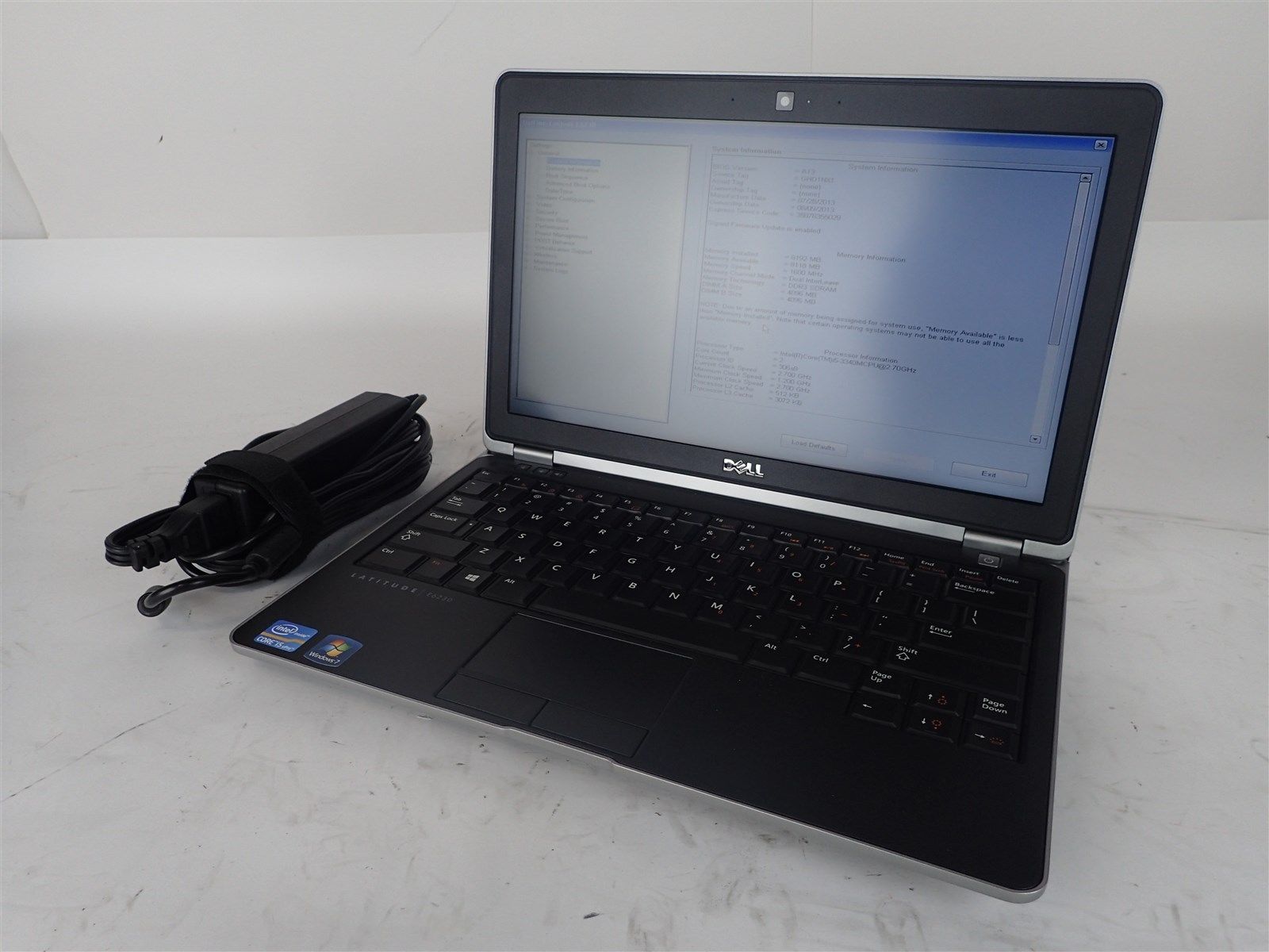
I am very pleased to announce that coreboot now supports the CompuLab Intense PC and MintBox 2! ??


Building coreboot
The instructions for building coreboot yourself can be found on the coreboot Wiki. You will need a Linux system with typical development packages installed such as build-essential.

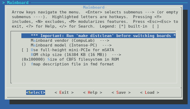
Select CompuLab and Intense-PC in the Mainboard section of the coreboot menuconfig:

You need to decide at this point whether you wish to use the internal full-height PCI-Express slot for mSATA or as PCI-Express:

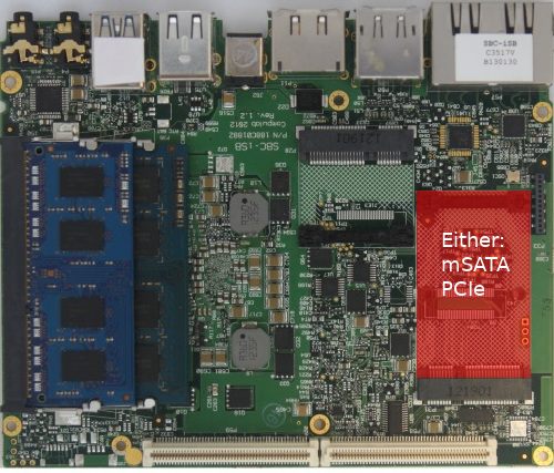
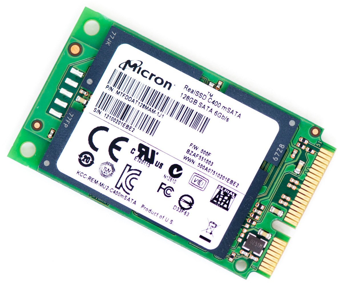
If you have not installed an additional mSATA SSD in your Intense PC, then you do not need to select this option. Selecting the mSATA option is only required if you have installed an mSATA SSD and want to use it in the Intense PC:

Because coreboot does not have full support for the embedded controller (EC) in the Intense PC right now, the choice of using mSATA or PCIe cannot be made at runtime. If later you wish to change the function of the slot, you need to rebuild coreboot while selecting the appropriate choice of mSATA or PCIe.

Note that the mSATA port is limited to SATA 3Gbps speeds. This is a hardware limitation of the Intense PC design, and cannot be changed by flashing coreboot.


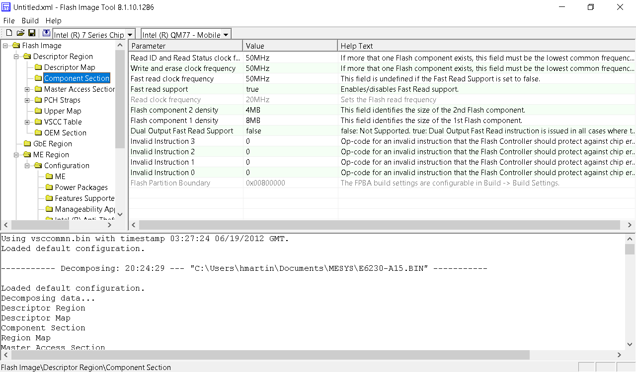
It is important to include the Firmware Descriptor Table (FDT), ME, and GbE regions of flash. Specify these files in the Chipset section:

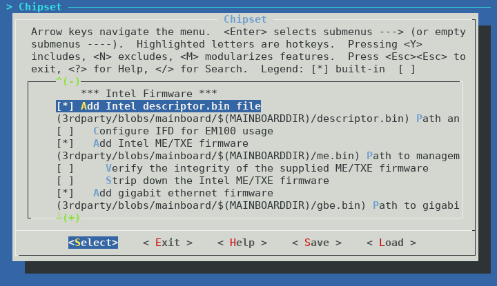
You can choose yourself if you want to run me_cleaner on the ME or not. Note that if you choose to run me_cleaner, all SATA ports will cease to function. This is not a coreboot specific bug, the same behaviour occurs on the CompuLab firmware when me_cleaner is run. It may or may not be possible to fix this issue, more research is needed to understand the root cause.


If you want to have video during POST, you also need to include the Intel VGA BIOS in the image. Specify this in the Devices section:

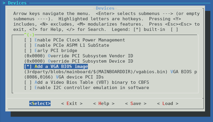
In theory coreboot graphics init is supposed to initialize the Intel HD graphics without the need for the VGA BIOS, however without the VGA BIOS I was unable to get any video output until the Linux kernel started booting. This makes using the bootloader menu or troubleshooting pre-boot issues very difficult.


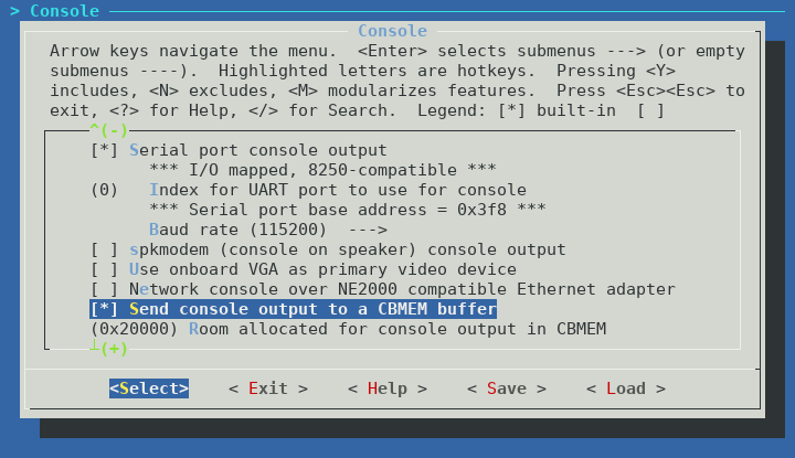
I would recommend you enable logging to cbmem at a minimum. This will allow you to access the coreboot boot log in Linux using the cbmem utility. If you have trouble booting the Intense PC after flashing coreboot, I would recommend you enable logging to UART, and use the included serial dongle to debug coreboot via RS-232 (115200n8). UART support for the Intense PC should be accepted to coreboot master shortly.


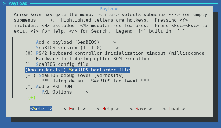
The default boot order of SeaBIOS seems to be SATA HDD if present, then PXE boot (if compiled with iPXE). It is possible and easy to change this, by specifying a bootorder file to include in cbfs when building coreboot.

I have created a boot order file which searches for boot devices in the following order:

  1. USB 2.0 devices
  2. USB 3.0 devices
  3. SATA devices (in order: 2.5″ internal, mSATA, eSATA, FACE module)
  4. iPXE

You can download the bootorder file and include it in cbfs. If you don’t include iPXE as a payload, remove the last line of the bootorder.txt file. If you are not building SeaBIOS as a payload, then you do not require this file.


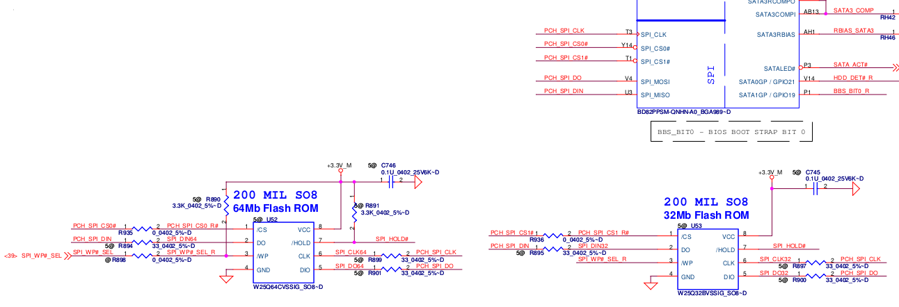
After building coreboot, but before flashing, we need to split the coreboot.rom file into two 8MB files. This is because the Intense PC has two 8MB NOR flash chips totaling 16MB.

Split the coreboot.rom file into two 8MB files “SC1.bin” and “SC2.bin” using dd:
$ dd if=build/coreboot.rom of=SC1.bin bs=1M count=8
$ dd if=build/coreboot.rom of=SC2.bin bs=1M skip=8


Extracting binary firmware components
You may notice above that several portions of the initial Intense PC firmware are required to successfully build coreboot. The Intel Descriptor file (otherwise known as the Flash Descriptor Table or FDT), Management Engine firmware, Gigabit Ethernet region, and VGA BIOS.

If you have not yet installed the CompuLab firmware update to address CVE-2017-8083, you should be able to dump the entire firmware using flashrom in Linux:
# flashrom -p internal:laptop=force_I_want_a_brick -r intense_pc.bin

If you have already patched your system, then flashrom will be unable to dump the firmware:
Enabling flash write... Warning: SPI Configuration Lockdown activated.
FREG0: Warning: Flash Descriptor region (0x00000000-0x00000fff) is read-only.
FREG2: Warning: Management Engine region (0x00003000-0x00cfffff) is locked.

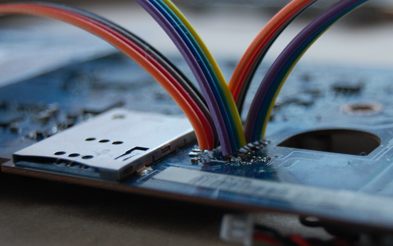
You will have to use a hardware method to dump the firmware from the chips. As an example, using a ch341 based SPI programmer and flashrom:
# flashrom -p ch341a_spi -r sc1.bin
# flashrom -p ch341a_spi -r sc2.bin

Confirm that sc1.bin contains the start of the flash descriptor:
$ hexdump -C sc1.bin | head -2
00000000 ff ff ff ff ff ff ff ff ff ff ff ff ff ff ff ff |................|
00000010 5a a5 f0 0f 03 01 04 03 06 02 10 12 20 01 21 00 |Z........... .!.|

Do not forget to concatenate the firmware together into a 16MB image before running ifdtool:
$ cat sc1.bin sc2.bin > intense_pc.bin

You can then extract the regions from the firmware using ifdtool (included in coreboot/utils):
$ ifdutil -x intense_pc.bin

The output of ifdtool should appear as follows:
File intense_pc.bin is 16777216 bytes
Flash Region 0 (Flash Descriptor): 00000000 - 00000fff
Flash Region 1 (BIOS): 00d00000 - 00ffffff
Flash Region 2 (Intel ME): 00003000 - 00cfffff
Flash Region 3 (GbE): 00001000 - 00002fff
Flash Region 4 (Platform Data): 00fff000 - 00000fff (unused)

ifdtool will output files for each flash region. For building coreboot, we are interested in the following regions:
flashregion_0_flashdescriptor.bin
flashregion_2_intel_me.bin
flashregion_3_gbe.bin


If ifdtool doesn’t work for some reason, verify that you have concatenated the firmware files in the correct order. Or, if you don’t want to use ifdtool, you can split it manually using dd.

Intel Descriptor file/FDT:
$ dd if=intense_pc.bin of=descriptor.bin bs=4096 count=1

Management Engine:
$ dd if=intense_pc.bin of=me.bin bs=4096 count=1028 skip=3

Gigabit Ethernet region:
$ dd if=intense_pc.bin of=gbe.bin bs=4096 count=2 skip=1


You can extract the VGA BIOS from within Linux. First, verify the PCI ID of the Intel integrated graphics controller. On the Intense PC, this should be 00:02.0:
$ lspci | grep Graphics
00:02.0 VGA compatible controller [0300]: Intel Corporation 3rd Gen Core processor Graphics Controller [8086:0166] (rev 09)

Once you have confirmed the PCI ID, you can dump the VGA BIOS to a file:
# echo 1 > /sys/devices/pci0000:00/0000:00:02.0/rom
# cat /sys/devices/pci0000:00/0000:00:02.0/rom > vgabios.bin
# echo 0 > /sys/devices/pci0000:00/0000:00:02.0/rom

vgabios.bin should be exactly 65536 bytes and begin similar to the following:
$ hexdump -C vgabios.bin | head -2
00000000 55 aa 78 e9 b8 e9 30 30 30 30 30 30 30 30 30 30 |U.x...0000000000|
00000010 30 30 90 24 e9 a9 23 a0 40 00 b0 0a 30 30 49 42 |00.$..#[email protected]|

It is recommended to also dump the video bios table (VBT) to a file to include in cbfs, as the VBT table is expected by Windows:
# cat /sys/kernel/debug/dri/0/i915_vbt > vbt.bin

vbt.bin should be exactly 6144 bytes and look similar to the following:
$ hexdump -C vbt.bin | head -2
00000000 24 56 42 54 20 53 4e 42 2f 49 56 42 2d 4d 4f 42 |$VBT SNB/IVB-MOB|
00000010 49 4c 45 20 64 00 30 00 b8 10 e7 00 30 00 00 00 |ILE d.0.....0...|


Flashing coreboot

The following instructions are provided AS-IS and with no warranty, express or implied. Flashing coreboot can turn your computer into a brick and will void your warranty. By following these instructions you acknowledge these risks and assume all liability.

To flash coreboot onto your Intense PC, you will need an SPI programmer supported by flashrom.

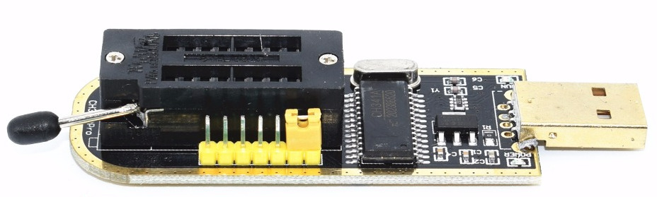
An inexpensive option is a CH341 based SPI programmer (<$2 USD from eBay/AliExpress):

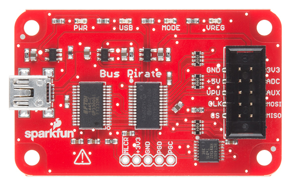
Another useful tool which can also be used for flashing is the Bus Pirate (~$25 USD):

The Raspberry Pi should also work. Here is a detailed post on how to use the Raspberry Pi to flash firmware to a NOR flash.

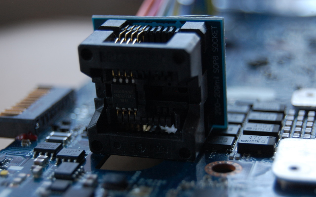
Unfortunately for us, the NOR flash in the Intense PC is in a WSON package (very very thin small outline no lead package) so a SOIC clip or SOIC socket will not work.

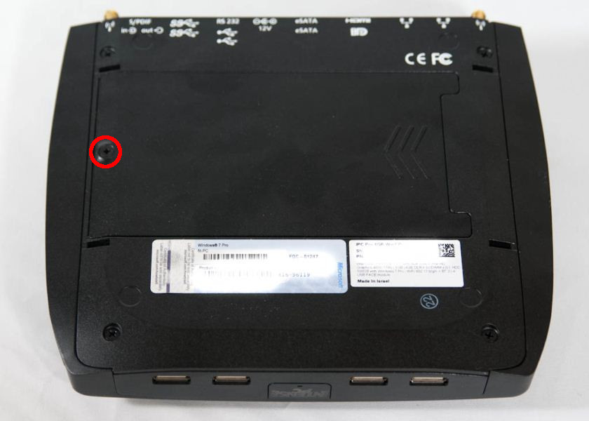
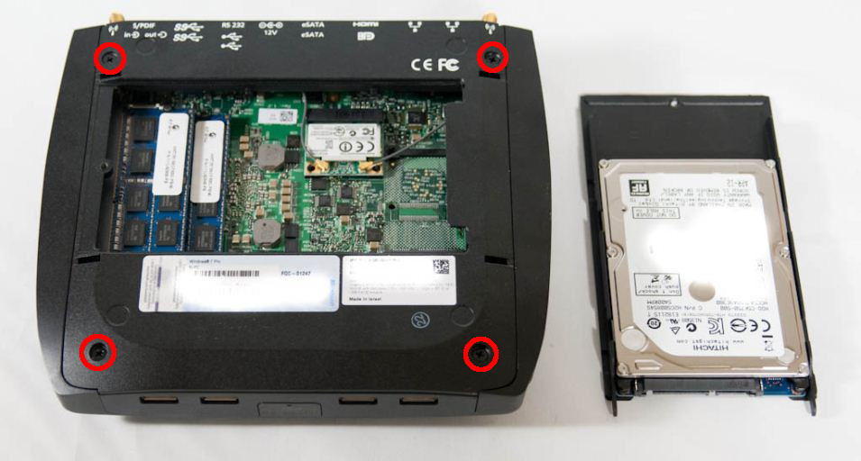
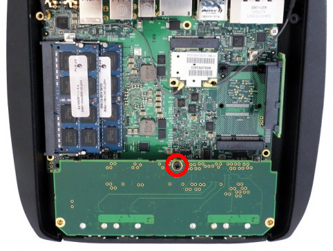
Because the Intense PC uses the chassis as a heat sink, you need to remove the motherboard from the Intense PC chassis to access the NOR flash. To do this, first remove the hard drive and hard drive carrier secured by a single screw:

Next, remove the 4 screws securing the bottom plate to the chassis:

Next, remove the retaining screw of the FACE module:

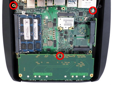
Next, remove the screw and two stand-offs securing the motherboard to the chassis. The screw is by the Ethernet ports, and the two stand-offs: one near the audio ports and one under the FACE module:

Disconnect the WiFi antennas (if installed) and disconnect the front panel connector near the SODIMM sockets. You should now be able to lift the motherboard out of the chassis.

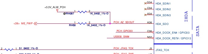
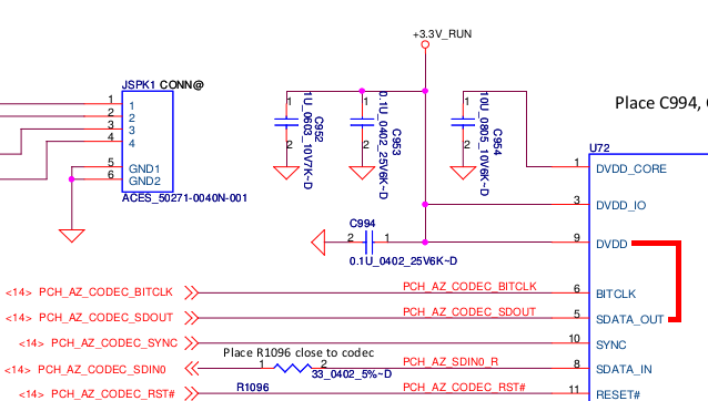
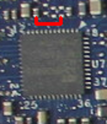
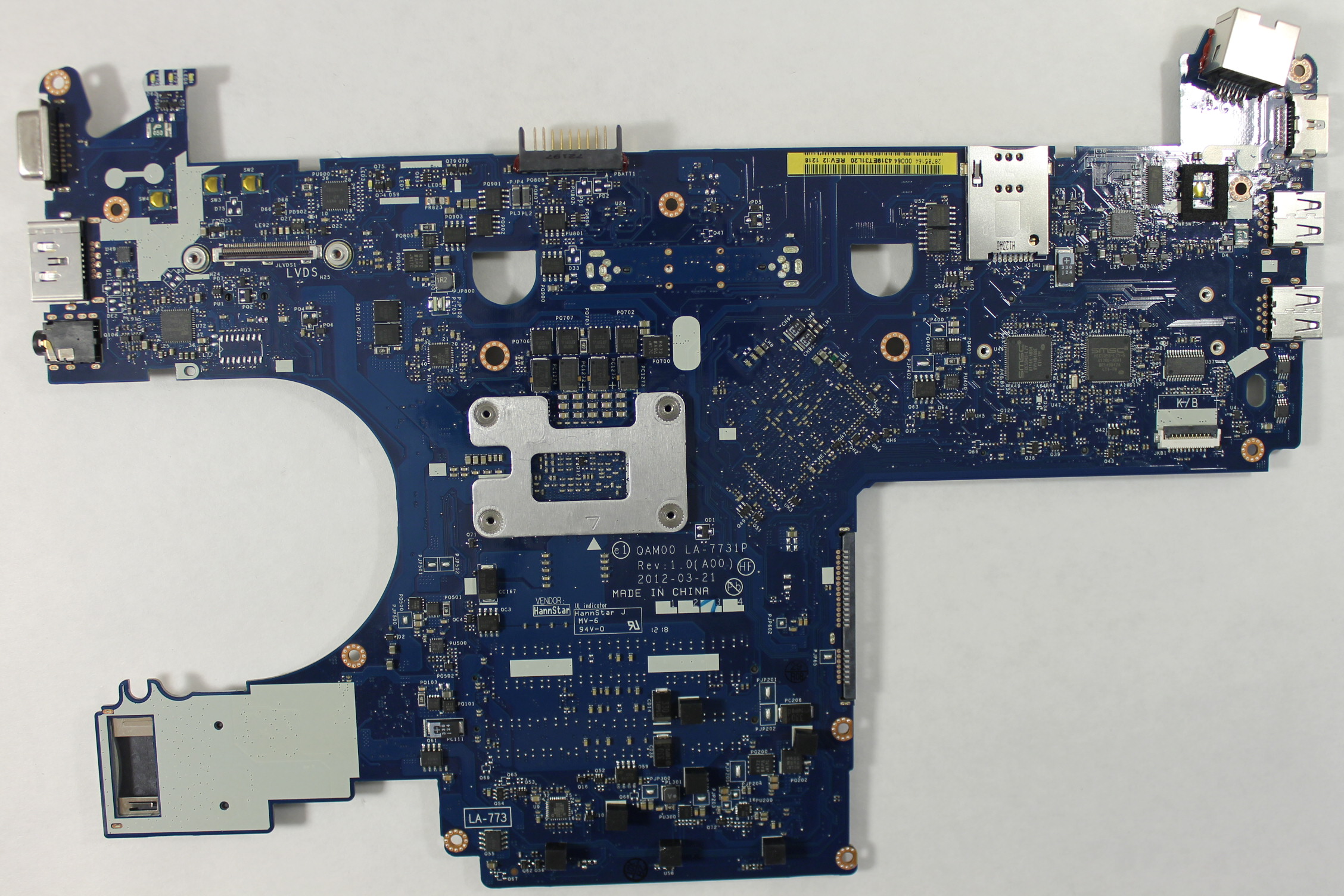
You will find the two NOR flash modules on the reverse side of the motherboard:

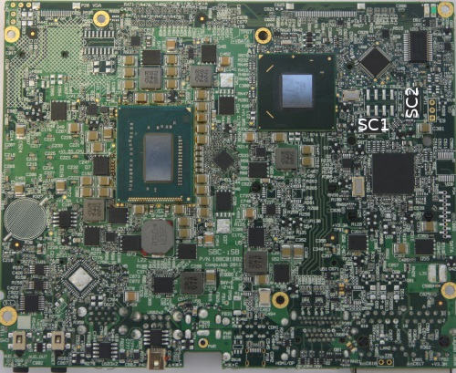
You will need to solder connections to the pads beside each chip to back up the original firmware and to flash coreboot.

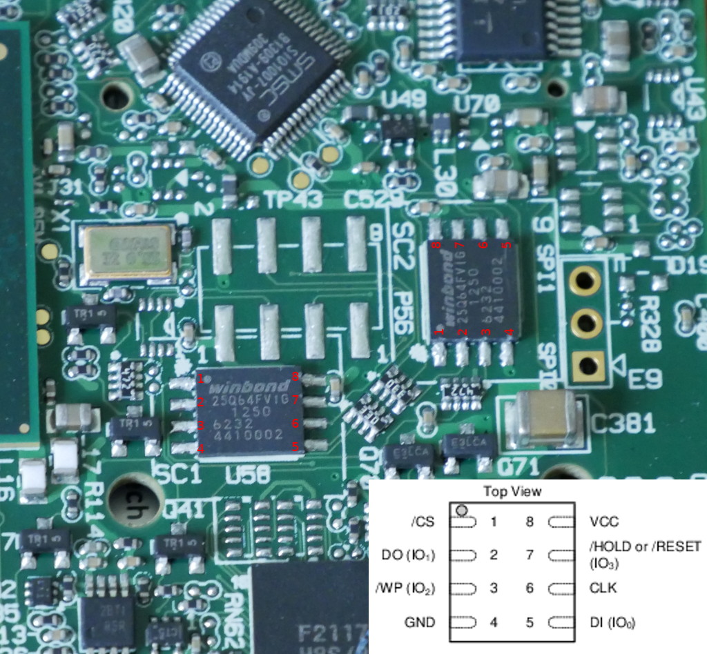
If you’re using the ch341 based programmer, then the flashrom commands would be the following:
For the NOR flash near SC1: $ sudo flashrom -p ch341a_spi -w SC1.bin
For the NOR flash near SC2: $ sudo flashrom -p ch341a_spi -w SC2.bin


Conclusion
If you value open-source software and want an alternative to the closed-source and infrequently updated CompuLab firmware, then coreboot is a great choice for the Intense PC/MintBox 2.

However building and flashing coreboot on the Intense PC is not without its risks. You will void your warranty and specialized equipment such as a soldering iron and SPI flashing tool are required.

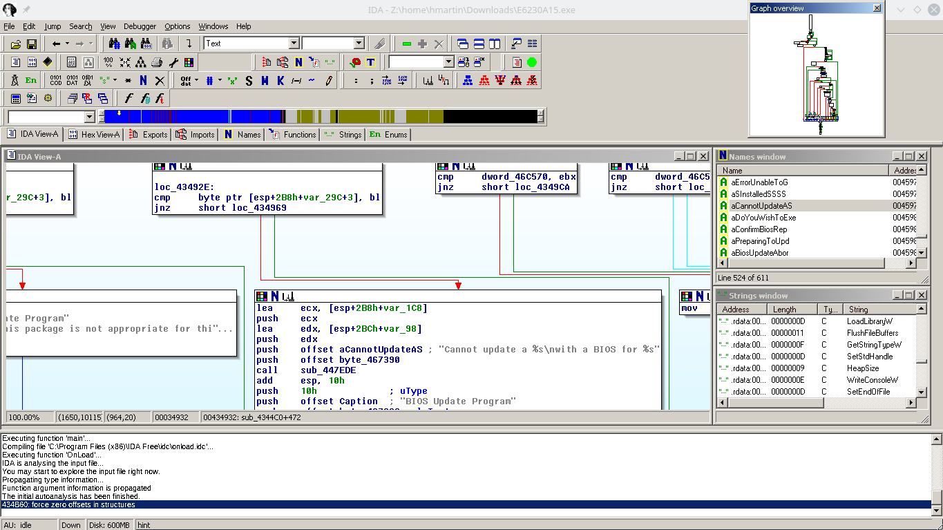
I was disappointed to find multiple vulnerabilities in CompuLab’s Intense PC firmware. These serious vulnerabilities and CompuLab’s rather lackluster response inspired me to port coreboot to the Intense PC.

I am not an expert on the inner workings of the x86 platform and boot process, so I could not have successfully completed this port without the assistance of the excellent autoport tool.


Coreboot advantages

  • ?Open-source firmware?
  • Better memory (RAM) compatibility than the CompuLab firmware
  • Memtest86+ and iPXE can be included as a payload in flash
  • Verified boot supported via vboot

Limitations

  • VBIOS is required if you want any video output before the kernel framebuffer is initialized
  • VGA hand-off to Windows is still not working
  • ME firmware is still necessary for most users as me_cleaner breaks SATA
  • Currently no easy path to support UEFI
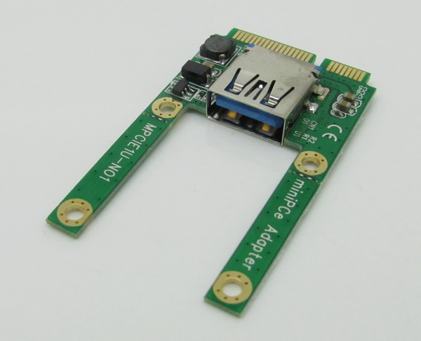
  • No FACE modules except for the included 4 port USB2.0 FACE module (FM-4USB) are supported (due to lack of additional FACE modules to test)

Please note that due to copyright concerns I cannot distribute binary firmware components such as the ME firmware or video BIOS. Additionally, for technical reasons I cannot provide a fully built, flashable coreboot image for your Intense PC. This is the reason for the “Extracting binary firmware components” section of the article.

If you experience issues building or using coreboot, please leave a comment or subscribe to the coreboot mailing list and ask your question there.

The coreboot project and I make no guarantee these instructions and the resulting firmware won’t turn your system into a fancy brick. The instructions produce a bootable firmware on my hardware (MintBox 2) at the time of writing, although this could change at some point in the future.

Please exercise caution and common sense when modifying system firmware and ensure you always have a backup of the original firmware on another device should something go wrong.

Reassembling a firmware from pieces

Working on firmware is always interesting. Modern x86 computers are incredibly complicated, due to the evolution of the architecture over the last 40 years, and it’s difficult to debug issues past “Well it doesn’t POST, better try something else.”

Unlike most ARM/MIPS systems, where you have a UART console or something to see output from u-boot, if you mess up the firmware on an x86, you’ll have a non-communicative brick on your hands.

Of course you can also have firmware issues on ARM/MIPS, if you manage to corrupt u-boot on SPI flash, but since u-boot is open and not proprietary it’s easy to rebuild it from source and flash it again to recover.

Not so in the PC world. UEFI is horrendously complex compared to u-boot, and Intel’s reference implementation known as TianoCore is usually “improved” by several middlemen before going into the final product.

Trammel Hudson’s excellent talk from 33c3 (slides) on Bootstrapping a slightly more secure laptop highlights the situation with UEFI quite well:

Farm to table firmware

In this case, we’ve got TianoCore from Intel, insyde adds some magic fairy dust, this goes to Compal (the ODM of this laptop), and finally Dell (who would probably also claim to add magic fairy dust). In the end there’s a lot of proprietary fairy dust floating around, and we probably wouldn’t be able to boot the laptop if we just build TianoCore from source.

TianoCore itself is open source and BSD licensed, which is why all the vendors use it. Intel manages porting TianoCore to their new platforms, and since it’s BSD licensed, it means that someone like insyde can take the working base from Intel and add their proprietary fairy dust without having to release the modified source code.

SPI flash
The start of flash contains a region called the Flash Descriptor (PDF; page 3) which is programmed at system manufacture and tells the system where different firmware components are present on flash. Think of it as a partition table for the system flash. Under normal circumstances, the flash descriptor prevents the user from reading and/or writing portions of ROM. If you try to use tools to read or write the ME regions of flash, you’ll get a error similar to this:

Error 26: The host CPU does not have read access to the target flash area. To en
able read access for this operation you must modify the descriptor settings to g
ive host access to this region.

And this makes sense. If the system allowed unrestricted write access it would be trivial for some malware to write itself into the system firmware, and then you’d have a persistent rootkit. In my opinion, blocking the ability to read portions of the firmware serves no purpose except to discourage reverse engineering attempts.

Thankfully, there is a method known as Flash Descriptor Security Override Strap which can be used to disable the flash descriptor protection.

The first step is to locate the ME_FWP pin in the circuit diagram:
Override Strap

Now that we’ve located the pin on the logical diagram, we need to find the HDA chip itself so we can see which pins we need to bridge to disable the flash descriptor lock on the ME region:
la-7731p_sda

In this case, it’s most convenient for us to short pins 5 and 9:
la-7731p_hda

You could also short pins 1 and 5, but this requires a very steady hand and small instrument. However pins 5 and 9 are connected to surface mount components located away from the chip. These components (a capacitor and a pad) are much easier to access with a wire:
la_7731p_pin5_pin9

Amazingly, this area can be accessed without completely disassembling the laptop. Just taking off the palm rest and keyboard, which is about 8 screws, is enough to access the pins. They’re right under the LVDS cable to the display. Thanks, Compal!

At this point, I have two options:

  1. Find or buy an SPI dump online and flash that
  2. Find a way to dump the firmware from the working laptop without soldering

As you read in the previous post, I only managed to find an E6320 SPI dump online, and ended up with a laptop that worked-ish. I tried for many hours, but I wasn’t able to find any free SPI dumps for the E6230 online. After seeing many forums promising to sell you the firmware for outrageous prices, I finally found one that wanted only 8 złoty ($2) to download the SPI dump for the E6230. Principles be damned, I’ve wasted enough time trying to get this to work. I paid up and downloaded the files for the 4MB and 8MB chips.

Did I really get a valid firmware for $2? Yes!

But it’s BIOS A12, the current version is A16, but none of the Dell update utilities work! I installed Windows to try the update tool from Dell, but the laptop just rebooted without updating the firmware. I tried from FreeDOS and again, the laptop would just reboot when it got to flashing. Hrmm…

So, at this point I’m going to cheat a little: I have a working E6230, but I decided when I started this that I would not touch it with a soldering iron or heat gun. If it ain’t broke, don’t fix it!

Can I get a full firmware dump from the working E6230?

Intel FPT

Intel FPT is a proprietary command-line utility created by Intel for flashing firmware files through the computer’s internal SPI flashing interface.

Alright, let’s go dump the firmware! First you need to remember to apply the Flash Descriptor Security Override Strap, or the CPU will block your read attempt to the ME region.

However, once we’ve done that, FPT will allow us to dump regions of flash to a file.

At first I tried to dump just the ME and BIOS, using the A12 firmware from above, I reflashed these regions using the FPT utility from FreeDOS. The verification of the BIOS region failed, and when I rebooted I had a brick again.

But, the FPT tool lets you dump all the regions at once! I dumped the entire flash, but now we’ve got a 12MB file and I don’t know where the split is between the 8MB and 4MB flash chips.

After more searching, I found the Intel ME System Tools, including a utility called Flash Image Tool, which allows you to import the firmware image file created by FPT.

Well, the flash component density matches what’s in the laptop, so I guess this is correct.

Flash Image Tool also lets you build a new firmware image:

Writing ROM image file “C:\Users\hmartin\Documents\MESYS\Flash Image Tool\v8.1.10.1286\Build\outimage.bin”.
Writing file “C:\Users\hmartin\Documents\MESYS\Flash Image Tool\v8.1.10.1286\Build\outimage(1).bin” (size = 8388608)
Writing file “C:\Users\hmartin\Documents\MESYS\Flash Image Tool\v8.1.10.1286\Build\outimage(2).bin” (size = 4194304)
Writing MAP file “C:\Users\hmartin\Documents\MESYS\Flash Image Tool\v8.1.10.1286\Build\outimage.map”.

Image size = 0xC00000 bytes

Interesting… outimage(1).bin is exactly 8192KB, and outimage(2).bin is exactly 4096KB. I wrote these two images to the respective chips and put them into the laptop. The moment of truth had arrived.

It boots!

When you’re trying to work through firmware issues, it’s really helpful to have the flash chip in a socket. Soldering and desoldering gets really old when you have to do it more than a couple of times.

Thoughts on the sale of firmware images

I’m against the sale of these firmware images. I realize that it takes a non-zero amount of time to get the image, but the whole experience of BIOS forums just leaves you feeling dirty. You have no way to verify before payment that the files they’re providing even work. Combine this with the fact that most websites want $10-$20 for the SPI dump, the experience leaves a bad taste in your mouth.

Is it worth it to pay? It depends entirely on your willingness to pay. Is this your only computer? Do you need it working now? How much of your own time are you willing to invest to learn about UEFI firmware? I’ve probably put 20 hours into this project, and I still don’t understand the internals of UEFI.

The wrong way to clear a BIOS password

I was browsing on eBay and ran into a listing for a Dell E6230. By now you might guess where this is leading:

Dell Latitude E6230 12.5″ i3-2350M 2.3GHz 4GB RAM Admin Pass Set AS IS READ!

s-l1600

The whole laptop, everything working perfectly, except… it has a firmware password set, and the seller doesn’t know the password. Well no bother, it’s cheap (83 EUR), I know how to flash SPI chips. Should be a piece of cake to clear this password! I also had an E6230 motherboard with a Core i5-3320M which I had found on eBay for 40 EUR, so my plan was to swap the boards, and then work on clearing the password.

These boards contain two flash chips: Winbond 64Mbit (8MB, U52) and Winbond 32Mbit (4MB, U53) located to the left of the SIM card slot.

f_0020914

The first step was to dump the SPI flash from U52 and U53 on both boards as a backup before flashing anything. This seemingly went well, but when I flashed the i5-3320M firmware dumps to the board with the i3-2350M, I had a brick.

It turns out that several of the pins to each chip are connected to the same pins in the PCH. Important pins like Data Out, Clock, and Data In are shared:

PCH SPI wiring

U52 and U53 share data out, data in, and clock lines to the PCH


I’m not sure exactly what happened, but my guess is that by leaving the flash soldered to the board, I somehow managed to get data from both chips. Alarms should have been going off in my head when my SPI reader dumped 8MB from a 4MB chip.

Not wanting to risk wrecking the i5-3320M board by desoldering the flash, I turned to the internet and discovered the terrible world of BIOS image dumps. It’s nearly impossible to find any website offering SPI dumps for free. Of course you can download the firmware update tool from the manufacturer, but those are meant to be run only on the intended hardware, and they only contain regions of the SPI flash like the UEFI firmware and Intel Management Engine.

I was able to find an SPI dump of the E6320, which is a 13.3″ laptop one generation previous to the E6230 (12.5″). As I had nothing to lose, I desoldered U52 and U53 and flashed the E6320 images to each chip. To my great surprise, the board passed POST, albeit with a warning about unsupported hardware. I was even able to enter the UEFI setup utility.

But now I am running a firmware intended for a completely different laptop. The E6320 has a QM67 (6 series) chipset, and the E6320 has a QM77 (7 series) chipset. The USB 3 ports on the side don’t work, the internal SATA port doesn’t work, and PXE booting doesn’t work. The only port that seems to work, at all, is a Mini PCIe USB port:

mini_pcie-usb30-1_zps098e038b

My next thought was to try the Dell E6230 BIOS update tool, which can run from DOS. I put FreeDOS on a USB stick in the above adapter and installed that in the WWAN Mini PCIe slot. Unfortunately for me, Dell has put checks into the update utility to check that it’s running on the correct hardware. This makes total sense, if a user downloads the wrong update for their laptop, they shouldn’t end up with a brick.

However, it didn’t suit my purpose. I wanted Dell’s BIOS update utility to ignore the fact that it was running on an “E6320” and instead flash the firmware for the E6230, the actual hardware.

Having been foiled by Dell’s checks, I decided to load up the utility in IDA Pro to see if I could bypass the check. A bit of string searching and I found the target, a jnz:
ida_jnz

Changing this check to a jz and I tried again. This time the utility didn’t complain about the machine being an E6320, but as soon as the flashing process started, the laptop shut off. So what happened? My best guess is that Management Engine shut down the platform.

Management Engine
The Intel ME has existed since the mid-2000’s, and is now deeply integrated into all of Intel’s modern x86 SKUs. The ME can provide additional functionality like a TPM (implemented in firmware), cryptographic acceleration, DRM, as well as other patented and super duper proprietary stuff. There’s a fairly comprehensive feature list available on Wikipedia.

Since Intel doesn’t actually release documents on the ME, it’s hard to come by actual information on the inner workings. It’s also why some libre people are concerned about buying newer laptops: the ME is integrated into the PCH, cannot be disabled, runs an OS with direct memory access to system RAM and has never been audited.

Trammell Hudson is currently experimenting with coreboot on the Lenovo X230, and it seems like there’s a non-zero chance that he’ll succeed in disabling the ME.

Anyway, I was on vacation earlier this year and had lots of time to kill in airports/planes/trains so I read a book about the Intel ME called “Platform Embedded Security Technology Revealed” You can download the ebook for free as a PDF or EPUB from the publisher.

Using knowledge from the above book, we can conclude that the security number of the Series 8 ME firmware must be equal to the security number of Series 7 firmware, or the ME would not allow the platform to power on.

Unfortunately, the updater managed to overwrite something important in flash before the ME cut power, because now I’m stuck with a brick again.

Stay tuned for part 2!