Working on firmware is always interesting. Modern x86 computers are incredibly complicated, due to the evolution of the architecture over the last 40 years, and it’s difficult to debug issues past “Well it doesn’t POST, better try something else.”
Unlike most ARM/MIPS systems, where you have a UART console or something to see output from u-boot, if you mess up the firmware on an x86, you’ll have a non-communicative brick on your hands.
Of course you can also have firmware issues on ARM/MIPS, if you manage to corrupt u-boot on SPI flash, but since u-boot is open and not proprietary it’s easy to rebuild it from source and flash it again to recover.
Not so in the PC world. UEFI is horrendously complex compared to u-boot, and Intel’s reference implementation known as TianoCore is usually “improved” by several middlemen before going into the final product.
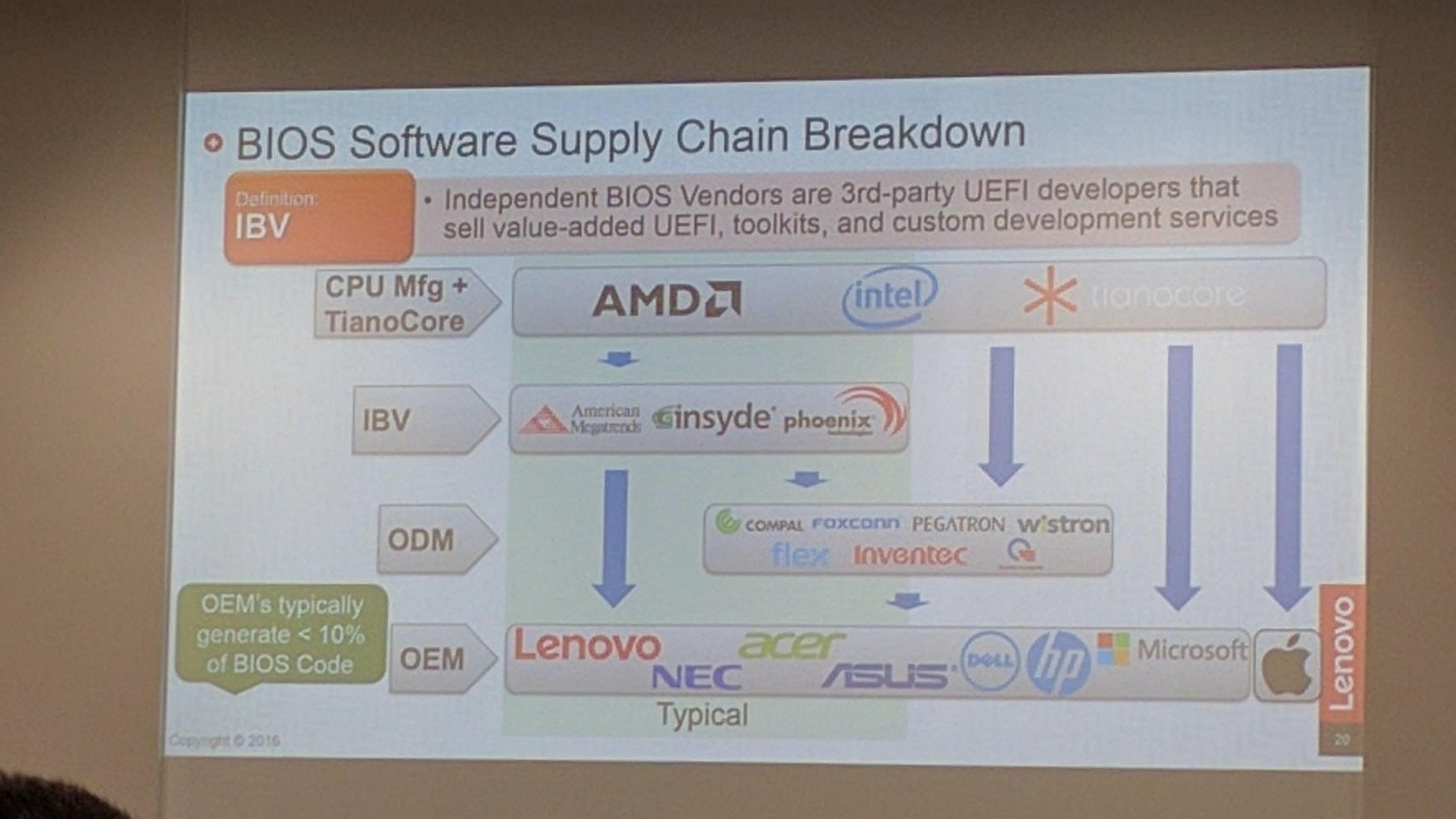
Trammel Hudson’s excellent talk from 33c3 (slides) on Bootstrapping a slightly more secure laptop highlights the situation with UEFI quite well:
In this case, we’ve got TianoCore from Intel, insyde adds some magic fairy dust, this goes to Compal (the ODM of this laptop), and finally Dell (who would probably also claim to add magic fairy dust). In the end there’s a lot of proprietary fairy dust floating around, and we probably wouldn’t be able to boot the laptop if we just build TianoCore from source.
TianoCore itself is open source and BSD licensed, which is why all the vendors use it. Intel manages porting TianoCore to their new platforms, and since it’s BSD licensed, it means that someone like insyde can take the working base from Intel and add their proprietary fairy dust without having to release the modified source code.
SPI flash
The start of flash contains a region called the Flash Descriptor (PDF; page 3) which is programmed at system manufacture and tells the system where different firmware components are present on flash. Think of it as a partition table for the system flash. Under normal circumstances, the flash descriptor prevents the user from reading and/or writing portions of ROM. If you try to use tools to read or write the ME regions of flash, you’ll get a error similar to this:
Error 26: The host CPU does not have read access to the target flash area. To en
able read access for this operation you must modify the descriptor settings to g
ive host access to this region.
And this makes sense. If the system allowed unrestricted write access it would be trivial for some malware to write itself into the system firmware, and then you’d have a persistent rootkit. In my opinion, blocking the ability to read portions of the firmware serves no purpose except to discourage reverse engineering attempts.
Thankfully, there is a method known as Flash Descriptor Security Override Strap which can be used to disable the flash descriptor protection.
The first step is to locate the ME_FWP pin in the circuit diagram:

Now that we’ve located the pin on the logical diagram, we need to find the HDA chip itself so we can see which pins we need to bridge to disable the flash descriptor lock on the ME region:
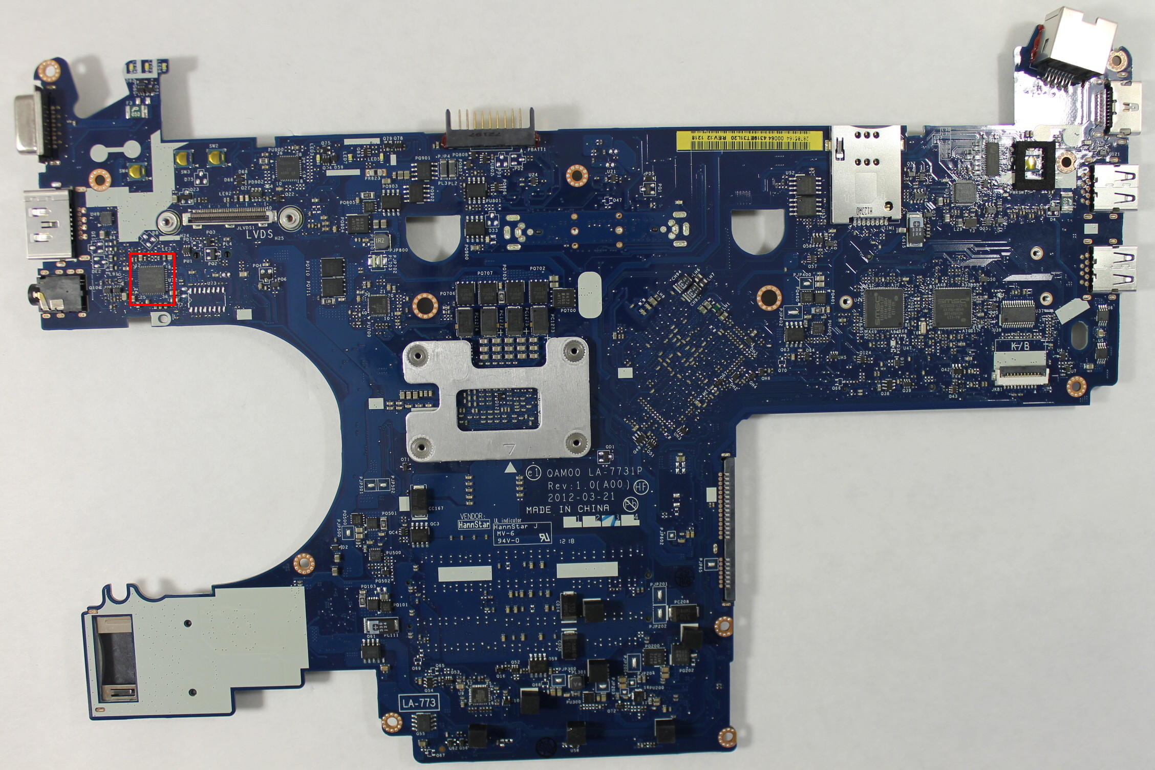
In this case, it’s most convenient for us to short pins 5 and 9:
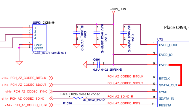
You could also short pins 1 and 5, but this requires a very steady hand and small instrument. However pins 5 and 9 are connected to surface mount components located away from the chip. These components (a capacitor and a pad) are much easier to access with a wire:
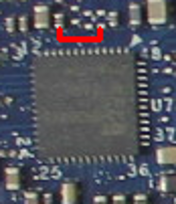
Amazingly, this area can be accessed without completely disassembling the laptop. Just taking off the palm rest and keyboard, which is about 8 screws, is enough to access the pins. They’re right under the LVDS cable to the display. Thanks, Compal!
At this point, I have two options:
- Find or buy an SPI dump online and flash that
- Find a way to dump the firmware from the working laptop without soldering
As you read in the previous post, I only managed to find an E6320 SPI dump online, and ended up with a laptop that worked-ish. I tried for many hours, but I wasn’t able to find any free SPI dumps for the E6230 online. After seeing many forums promising to sell you the firmware for outrageous prices, I finally found one that wanted only 8 złoty ($2) to download the SPI dump for the E6230. Principles be damned, I’ve wasted enough time trying to get this to work. I paid up and downloaded the files for the 4MB and 8MB chips.
Did I really get a valid firmware for $2? Yes!
But it’s BIOS A12, the current version is A16, but none of the Dell update utilities work! I installed Windows to try the update tool from Dell, but the laptop just rebooted without updating the firmware. I tried from FreeDOS and again, the laptop would just reboot when it got to flashing. Hrmm…
So, at this point I’m going to cheat a little: I have a working E6230, but I decided when I started this that I would not touch it with a soldering iron or heat gun. If it ain’t broke, don’t fix it!
Can I get a full firmware dump from the working E6230?
Intel FPT
Intel FPT is a proprietary command-line utility created by Intel for flashing firmware files through the computer’s internal SPI flashing interface.
Alright, let’s go dump the firmware! First you need to remember to apply the Flash Descriptor Security Override Strap, or the CPU will block your read attempt to the ME region.
However, once we’ve done that, FPT will allow us to dump regions of flash to a file.
At first I tried to dump just the ME and BIOS, using the A12 firmware from above, I reflashed these regions using the FPT utility from FreeDOS. The verification of the BIOS region failed, and when I rebooted I had a brick again.
But, the FPT tool lets you dump all the regions at once! I dumped the entire flash, but now we’ve got a 12MB file and I don’t know where the split is between the 8MB and 4MB flash chips.
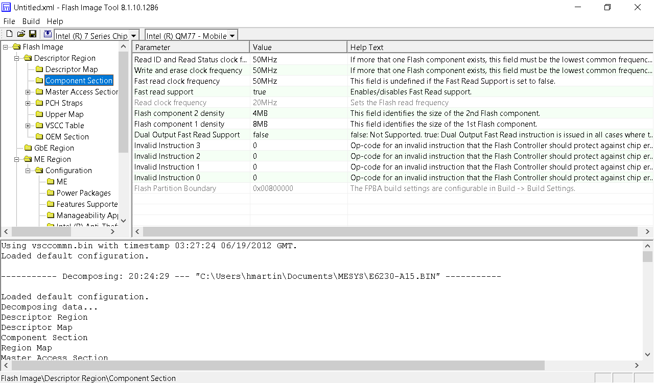
After more searching, I found the Intel ME System Tools, including a utility called Flash Image Tool, which allows you to import the firmware image file created by FPT.
Well, the flash component density matches what’s in the laptop, so I guess this is correct.
Flash Image Tool also lets you build a new firmware image:
Writing ROM image file “C:\Users\hmartin\Documents\MESYS\Flash Image Tool\v8.1.10.1286\Build\outimage.bin”.
Writing file “C:\Users\hmartin\Documents\MESYS\Flash Image Tool\v8.1.10.1286\Build\outimage(1).bin” (size = 8388608)
Writing file “C:\Users\hmartin\Documents\MESYS\Flash Image Tool\v8.1.10.1286\Build\outimage(2).bin” (size = 4194304)
Writing MAP file “C:\Users\hmartin\Documents\MESYS\Flash Image Tool\v8.1.10.1286\Build\outimage.map”.Image size = 0xC00000 bytes
Interesting… outimage(1).bin is exactly 8192KB, and outimage(2).bin is exactly 4096KB. I wrote these two images to the respective chips and put them into the laptop. The moment of truth had arrived.
It boots!
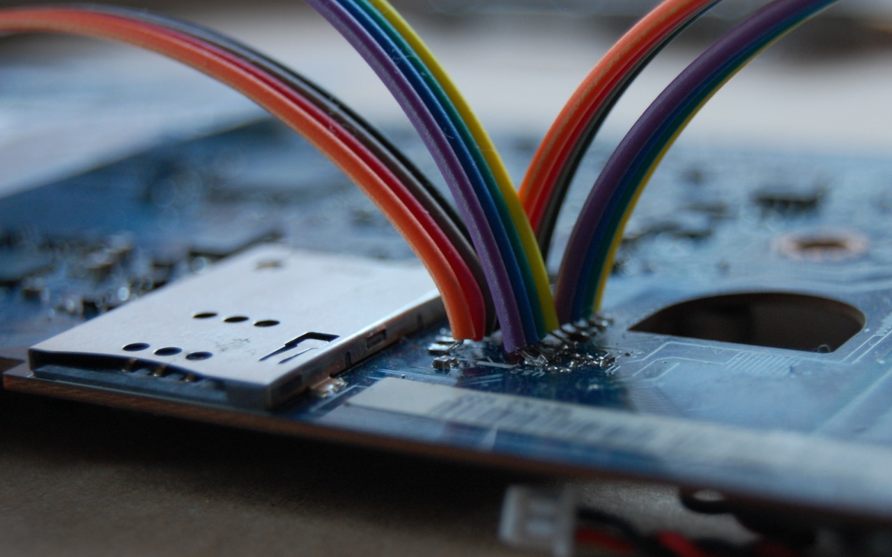
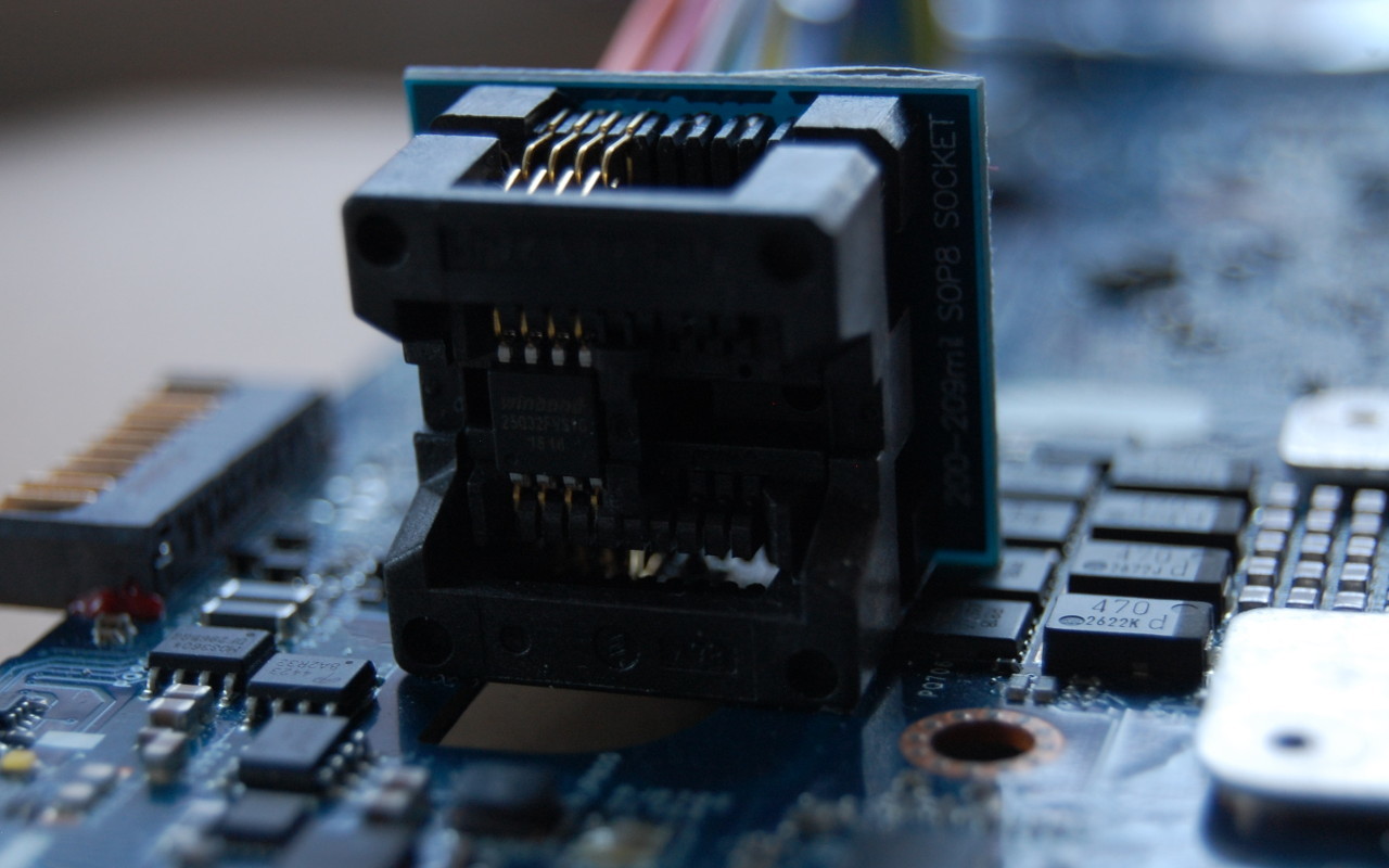
When you’re trying to work through firmware issues, it’s really helpful to have the flash chip in a socket. Soldering and desoldering gets really old when you have to do it more than a couple of times.
Thoughts on the sale of firmware images
I’m against the sale of these firmware images. I realize that it takes a non-zero amount of time to get the image, but the whole experience of BIOS forums just leaves you feeling dirty. You have no way to verify before payment that the files they’re providing even work. Combine this with the fact that most websites want $10-$20 for the SPI dump, the experience leaves a bad taste in your mouth.
Is it worth it to pay? It depends entirely on your willingness to pay. Is this your only computer? Do you need it working now? How much of your own time are you willing to invest to learn about UEFI firmware? I’ve probably put 20 hours into this project, and I still don’t understand the internals of UEFI.

Hi,
I have a newer laptop model (HP 15-BS576TX) which has unsupported bluetooth in Linux. The wifi-bluetooth module is Realtek RTL8723DE. The Wifi firmware and support is available in Linux. But, without bluetooth firmware, bluetooth remains unsupported in Linux. I also have Windows 10 installed and I extracted the Windows driver for bluetooth. What I hoped was bluetooth firmware or patchram whatever may be bundled along with the driver, and I cannot figure out the firmware. So, Is there a way to extract firmware from the Windows bluetooth driver provided by realtek or any way to get the firmware dump for bluetooth from a Windows machine. Thank you.
Hello my friend, I’m from argentina i’m into chip level repair in a broad range from notebooks to cellphones. I’m always stuyding , and reading different datasheets and docs , schematics trying to reverse engineer sometimes. Can you explain what’s the purpose of bridging DVDD and SATA OUT ?
The purpose of bridging DVDD and SDATA_OUT is to activate the Flash Descriptor Security Override Strap. The Flash Descriptor Security Override Strap on the PCH shares the pin with SDATA_OUT. By bridging SDATA_OUT to VCC, we activate the Override Strap so we can read the entire flash contents. Under normal operating conditions, the ME will prevent this action.