Category Archives: Firmware

Modifying the Cisco Meraki MS220-8P firmware

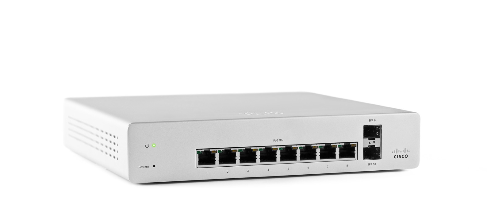
Following the analysis done by Leo Leung of the Cisco Meraki MS220-8P boot process, I wanted to share more information I’ve uncovered about the firmware source code, layout, and modification.

Cisco were not very forthcoming with the source code, and initially tried to claim that because the product was past the End of Sale, they were under no obligation to provide the source code. I am not a lawyer, but my understanding is that this claim is in violation of GPLv2 Section 3b, which states the the vendor must make the source code available for at least 3 years after the last distribution:

Accompany it with a written offer, valid for at least three years, to give any third party, for a charge no more than your cost of physically performing source distribution, a complete machine-readable copy of the corresponding source code, to be distributed under the terms of Sections 1 and 2 above on a medium customarily used for software interchange

https://opensource.org/licenses/gpl-2.0.php

I am extremely disappointed to see that Cisco is still not forthcoming with GPL source code. They have little to gain by being so difficult, and it is very disappointing to see them claiming they aren’t under obligation to provide the source code due to the product being discontinued.

To save anyone else the trouble of dragging the source code for Meraki Vitesse based switches (MS22, MS42, MS220, MS320) out of Cisco, I have mirrored the source code into 2 repositories on GitHub:

  • Stage 1 (NOR bootloader, kernel 3.18.122, includes RedBoot LinuxLoader)
  • Stage 2 (NAND firmware, kernel 3.18.123)

Please note: the kernel modules used to control the switch ASIC (vtss_core, merakiclick) are not included in the above source code. If you ever plan to build your own kernel and want to use the switch, you will need to extract the kernel modules corresponding to the above kernel versions from your switch.


My initial attempts to modify the firmware followed Leo’s instructions to disassemble the mtd region boot1. I was perplexed by the contents of the boot1-patched-post data that Leo’s script extracted from the image. The data in this region has an extremely high entropy:
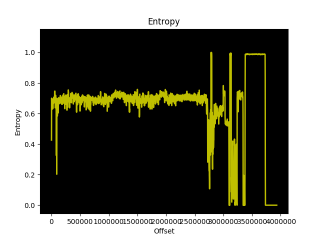
The data is quite large too, approximately 200KB or 5% of the boot1 region. That’s a lot of space to give up on an embedded system for no apparent reason!

I decided to zero out the contents of this boot1-patched-post section and see what effect it would have on the boot process of the switch. The result was a kernel panic, cannot open initrd:

[    2.537000] devtmpfs: error mounting -2
[    2.541000] Warning: unable to open an initial console.
[    2.548000] VFS: Cannot open root device "(null)" or unknown-block(0,0): error -2
[    2.556000] Please append a correct "root=" boot option; here are the available partitions:
[    2.564000] 1f00          131072 mtdblock0  (driver?)
...
[    2.674000] 1f15            2670 mtdblock21  (driver?)
[    2.679000] mkp_lg: VFS: Unable to mount root fs on unknown-block(0,0)
[    2.679000] Kernel panic - not syncing: VFS: Unable to mount root fs on unknown-block(0,0)

So the kernel can no longer find the initramfs, even though the XZ archive is still present in the region. This got me thinking that the region must contain information the kernel uses to extract the XZ compressed initrd.

The build instructions I received from Meraki with the source code stated:

To build OpenWRT firmware:

cd meraki-firmware/openwrt
cp config-elemental-3.18 .config
make oldconfig
make -j1 BOARD=elemental-3.18 OPENWRT_EXTRA_BOARD_SUFFIX=_3.18


To build Linux-3.18 kernel:

cd meraki-firmware/linux-3.18
cp ../openwrt/target/linux/elemental-3.18/config .config
make CROSS_COMPILE=../openwrt/staging_dir_mipsel_nofpu_3.18/bin/mipsel-linux-musl- ARCH=mips oldconfig

make CROSS_COMPILE=../openwrt/staging_dir_mipsel_nofpu_3.18/bin/mipsel-linux-musl- ARCH=mips prepare

touch rootlist
make CROSS_COMPILE=../openwrt/staging_dir_mipsel_nofpu_3.18/bin/mipsel-linux-musl- ARCH=mips vmlinux

After following these instructions and ending up with a vmlinux that was far too big to fit into the flash region, I figured out how to build the kernel such that it fits into the boot region. This also clarified what the contents of boot1-patched-post from Leo’s extraction script contains.

To start, if you are building the 3.18.122 kernel for the SPI flash (first stage boot, before kexec) you absolutely need a rootlist file. For the stock Meraki firmware, I have re-created the contents of the rootlist file:

file /bootsh ramdisk/bootsh 755 0 0
slink /init bootsh 777 0 0
file /kexec ramdisk/kexec 755 0 0
file /MERAKI_BUILD ramdisk/MERAKI_BUILD 755 0 0
dir /bootroot 755 0 0
dir /dev 755 0 0
slink /lib bootroot/lib 777 0 0
slink /etc/ bootroot/etc 777 0 0
slink /usr bootroot/usr 777 0 0
slink /sbin bootroot/sbin 777 0 0
slink /bin bootroot/bin 777 0 0

The Meraki provided instructions produce an ELF vmlinux, which is not what at all what the switch is booting. You must use objcopy to strip vmlinux before you can get it to what the switch expects in the firmware:

mipsel-linux-musl-objcopy -O binary -S vmlinux vmlinux.bin

By following the above steps, building the kernel with the above rootlist file contents and stripping vmlinux with objcopy, vmlinux.bin is the data that goes into the boot1 region immediately after the 32 byte header. Pad the header + vmlinux.bin with zeros to ensure it is 3932160 bytes total.

Aside: You’re probably not interested in including the same files in your ramdisk as the stock Meraki firmware. Unless you have modified the NAND image to spawn a console and kill their management daemons, you’ll have the same end result as the stock firmware. However, it is a useful test to ensure that you can build and boot the kernel yourself:

Linux version 3.18.122-meraki-elemental (hmartin@alp) (gcc version 5.4.0 (GCC) ) #4 Sun Mar 1 14:44:24 UTC 2020

The meraki_stock branch of the 3.18.122 repository includes the defconfig and rootlist file you need to build the 3.18.122 kernel.


Now onto more useful matters, modifying the bootloader. I grew tired of having CRC errors when testing my changes, so I patched the CRC check out of the bootloader. Later on, I decided I wanted to try booting 3.18.123 directly from NOR, except the stripped vmlinux is nearly 5MB, too large. So I patched out the boundary check in the bootloader. You can find both versions of the bootloader (without CRC and without CRC/boundary check) in the 3.18.122 repository on GitHub.

Meraki appears to supply a common firmware for all their Vitesse based switches. The MS220-8P is based on the luton26 ASIC, while the larger switches (MS22, MS42, MS220-24/48, and MS320-24/48) appear to be based on the Jaguar-1 ASIC. Since you don’t need the kernel modules for other models in the firmware, you can delete them (and other unnecessary Meraki daemons) and fit the entire firmware in roughly 8MB using XZ compressed squashfs.

With this combination, you can boot Linux 3.18.123 from NOR, with a squashfs on NOR:

[    0.000000] Kernel command line:  console=ttyS0,115200 mtdparts=m25p80:0x40000(loader1),0x4c0000(boot1),0x800000(bootubi),0x300000(jffs2) root=/dev/mtdblock3 rootfstype=squashfs ubi.mtd=gen_nand.0 mem=0x7FF0000 ramoops.mem_address=0x7FF0000 ramoops.mem_size=0x10000 ramoops.block_size=0x10000

Since the kernel version matches the modules shipped by Meraki in their firmware, you can load the modules required to manage the ASIC:

# lsmod
vc_click 251569 0 - Live 0xc35eb000 (PO)                                                                                                                                                   
elts_meraki 4132849 1 vc_click, Live 0xc30ab000 (PO)                                                                                                                                       
merakiclick 1587774 2 vc_click,elts_meraki, Live 0xc2854000 (O)                                                                                                                            
proclikefs 5189 2 merakiclick, Live 0xc007b000 (O)                                                                                                                                         
vtss_core 663855 1 vc_click, Live 0xc13f0000 (PO)

This approach is not without its own problems. The Meraki firmware expects / to be mounted rw, something that isn’t possible with squashfs.

In summary, with the following components you can boot directly from NOR, without touching NAND at all:

Please understand that I have not solved all the issues with this approach, and above resources are intended as a guide to encourage future development. To illustrate, here is a flashable image (see here) for your MS220-8P that illustrates booting entirely from NOR. Although I would like to caution you that this is a proof of concept, not a functional firmware. If you have any improvements please submit your pull request the meraki-builder repository!

The above information is the product of months of reverse engineering, development, and testing on an MS220-8P. It is my hope that by providing the GPL archive, my modifications, build scripts, and documentation that others will find a more elegant way to run the firmware entirely from NOR, which would significantly decrease the complexity to running a custom firmware on the MS220-8P.

That’s all for now. I will continue working on this project in the background and may have more updates in the future.
Resetting Supermicro X10 series BMC to factory defaults

If you’ve ever bought a used Supermicro motherboard and it came without the IPMI login reset to ADMIN/ADMIN, you may be wondering how you can reset IPMI to factory defaults without booting an OS.

Quick note before we continue: if you have an OS on the board, and have installed the IPMI tools for your OS, it’s easier to reset the IPMI username/password via those utilities than via the following method.

This method requires physical access and an SPI programmer like the ch341a or Raspberry Pi. A SOIC16 chip clip will also make life much easier. The ch341a and SOIC16 chip clip can be purchased online for <$10 USD from various sources (e.g. eBay, AliExpress).

Disclaimer: This information is provided without any warranty. Always take multiple physical backups of firmware before performing any modifications. I have only tested this on the Supermicro X10SLE-F motherboard as it is the only Supermicro board I own. However, looking at the REDFISH BMC update image available on Supermicro’s website, this method should be compatible with all X10 series motherboard BMC firmware.

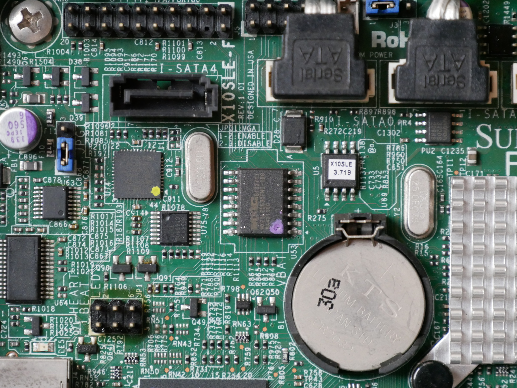
To start, we need to locate the BMC flash. On my X10 board, this is an SOIC16 chip from MXIC with a capacity of 32MB (256MBit).

U53 (SOIC16, 256MBit) contains the BMC firmware, U5 (SOIC8, 128MBit) contains the BIOS

Dump the contents of the BMC firmware using flashrom (using ch341a_spi):

$ flashrom -p ch341a_spi -r BMC.bin

I always dump the flash twice and compare the dumps using a hashing algorithm like sha1 or sha256, to confirm that both dumps are identical.

If they are not identical, check your physical connection to the chip and whether something on the board is receiving power from your SPI programmer.

Using binwalk, find the JFFS2 region. In Supermicro X10 firmwares, this appears to be from 0x100000 to 0x400000:

$ binwalk BMC.bin
DECIMAL       HEXADECIMAL     DESCRIPTION
--------------------------------------------------------------------------------
109381        0x1AB45         Certificate in DER format (x509 v3), header length: 4, sequence length: 12291
109541        0x1ABE5         Certificate in DER format (x509 v3), header length: 4, sequence length: 12291
109777        0x1ACD1         Certificate in DER format (x509 v3), header length: 4, sequence length: 12291
109913        0x1AD59         Certificate in DER format (x509 v3), header length: 4, sequence length: 12291
110057        0x1ADE9         Certificate in DER format (x509 v3), header length: 4, sequence length: 12291
112368        0x1B6F0         CRC32 polynomial table, little endian
1048576       0x100000        JFFS2 filesystem, little endian
4194304       0x400000        CramFS filesystem, little endian, size: 11915264 version 2 sorted_dirs CRC 0xD6771DEA, edition 0, 6818 blocks, 1038 files
20971520      0x1400000       uImage header, header size: 64 bytes, header CRC: 0xC5F4666A, created: 2015-10-05 10:52:56, image size: 1537322 bytes, Data Address: 0x40008000, Entry Point: 0x40008000, data CRC: 0x677BDAA8, OS: Linux, CPU: ARM, image type: OS Kernel Image, compression type: gzip, image name: "21400000"
20971584      0x1400040       gzip compressed data, maximum compression, has original file name: "linux.bin", from Unix, last modified: 2015-10-05 10:49:39
24117248      0x1700000       CramFS filesystem, little endian, size: 5435392 version 2 sorted_dirs CRC 0x43329740, edition 0, 2071 blocks, 309 files

To reset to factory defaults, simply overwrite the JFFS2 region with 0:

$ dd if=/dev/zero of=BMC.bin bs=1 seek=1048576 count=3145728 conv=notrunc

Reflash the modified firmware:

$ flashrom -p ch341a_spi -w BMC.bin

When you power up the board again, the BMC will re-create the JFFS2 region with the default credentials of ADMIN/ADMIN.

Editing the JFFS2 partition instead of overwriting it with zeros seems to invalidate a checksum somewhere, and this causes the BMC to re-initialize the JFFS2 region on the next boot. For that reason, I wouldn’t recommend extracting and editing the JFFS2 region, just zero it out.

Note: you will lose any licensed features in the BMC by resetting it to defaults using this method. However, Peter Kleissner did an amazing job reverse engineering the Supermicro license validation code, and using his work you can generate an IPMI license for your BMC.

With the licensed BIOS upgrade feature of IPMI, you can update the BIOS without ever needing to boot an OS, very handy for when your CPU revision is unsupported by an old BIOS release or if the board happens to have a corrupt BIOS image.

It should also be noted that the Supermicro BIOS updates available from their website appear to be directly flashable to SPI. You’ll lose some SMBIOS information if you use an SPI programmer to write directly to the SOIC8 containing the BIOS, but it can also help resolve some strange issues encountered after the IPMI BIOS upgrade (example below).

I hope this information is useful to anyone trying to get into their Supermicro BMC. Of course, requiring physical access and an SPI programmer is never as easy as resetting the BMC passwords from software and carries some risk that you may corrupt the BMC firmware.


There’s a thread on ServeTheHome about this motherboard if you have any further questions.

Debian on WD EX2100: Installation instructions

In the last article on this topic, I unbricked my Western Digital My Cloud EX2100 NAS and said I would provide instructions on how to install Debian. There are partial instructions for how to replace the stock u-boot with one that is capable of booting Debian from a USB stick, but following those instructions requires slightly more knowledge about how the boot process works and omits some important details.

Now that I have the EX2100 working again, I thought it would be good to provide a set of complete, concise installation instructions for anyone else with this hardware who is interested in running Debian (or another Linux) on it. These instructions are also available on the Doozan forum.


Uart
Before we begin installation of Debian, you will need a working uart connection to the EX2100.

There are two possible methods to connect via uart:

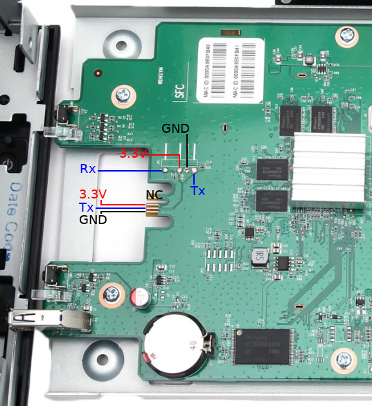
  1. solder a header to JP1 the PCB to expose Rx, Tx, and Gnd. This will require opening the enclosure and removing the PCB, which will void your warranty
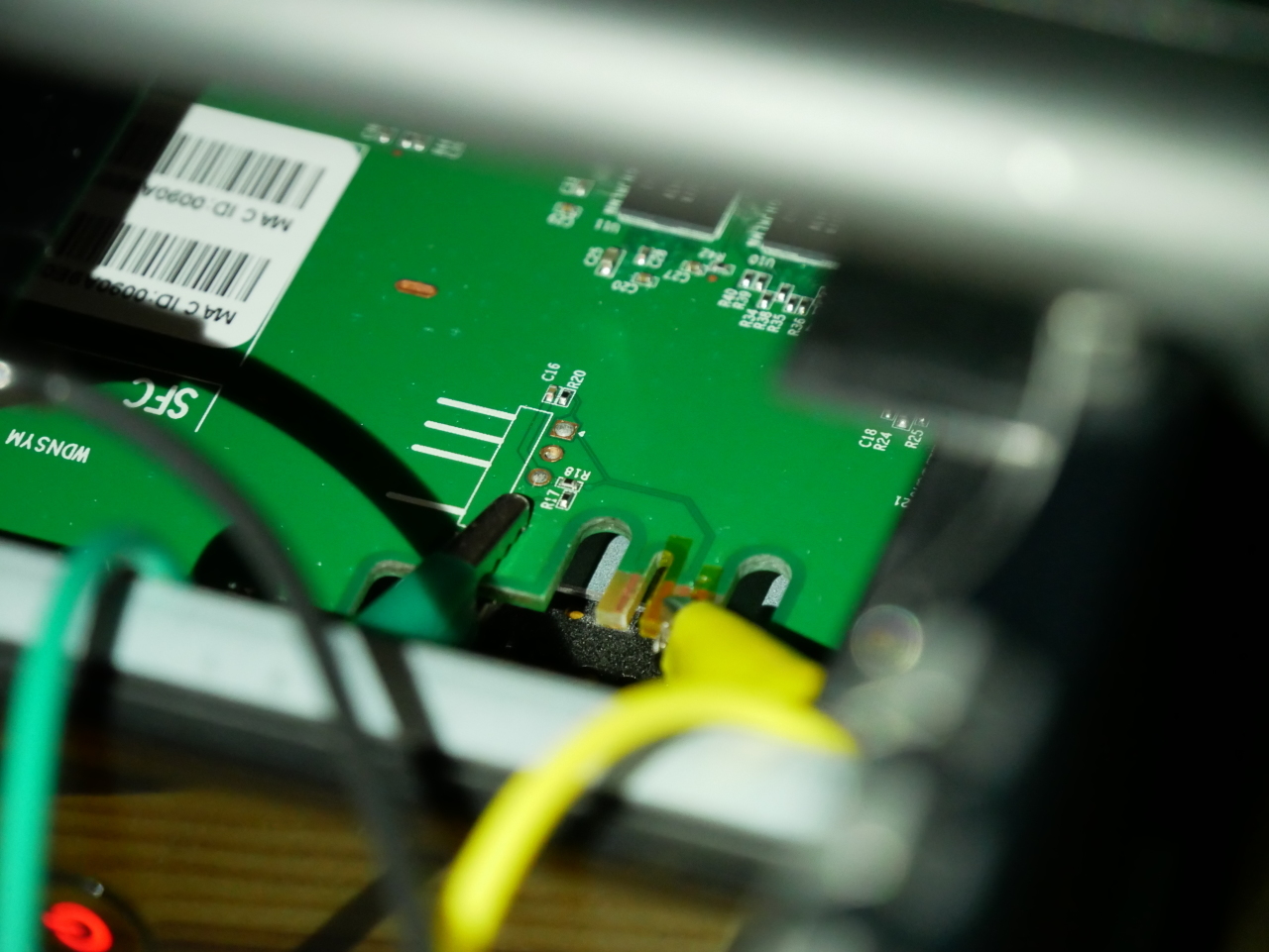
  2. Using kapton tape (tweezers, and patience), cover the 3.3V and GND pads on the front of the PCB. Use alligator clips to attach to the Tx contact, the Rx pad from JP1, and the chassis for ground. This method is not as reliable as soldering a header to JP1, but does not require disassembly and soldering as the area can be accessed by opening the hard drive bay doors

Test the connection by powering up the EX2100 with a USB to uart adapter or something like a Raspberry Pi. The uart operates at 115200n8.

You should immediately see output from u-boot (see sample below). If you don’t see any output, check your connections and ensure that you have not reversed the uart Tx/Rx.

Uart output

BootROM - 1.73
Booting from NAND flash

General initialization - Version: 1.0.0
Detected Device ID 6820
High speed PHY - Version: 2.0

Load WD Yosemite Serdes Config:
board SerDes lanes topology details:
| Lane # | Speed | Type |
--------------------------------
| 0 | 06 | SATA0 |
| 1 | 05 | PCIe0 |
| 2 | 06 | SATA1 |
| 3 | 05 | USB3 HOST1 |
| 4 | 05 | USB3 HOST0 |
| 5 | 00 | SGMII2 |
--------------------------------
PCIe, Idx 0: detected no link
High speed PHY - Ended Successfully
DDR3 Training Sequence - Ver TIP-1.26.0
mvSysEnvGetTopologyUpdateInfo: TWSI Read failed
DDR3 Training Sequence - Switching XBAR Window to FastPath Window
DDR3 Training Sequence - Ended Successfully
BootROM: Image checksum verification PASSED

__ __ _ _
| \/ | __ _ _ ____ _____| | |
| |\/| |/ _` | '__\ \ / / _ \ | |
| | | | (_| | | \ V / __/ | |
|_| |_|\__,_|_| \_/ \___|_|_|
_ _ ____ _
| | | | | __ ) ___ ___ | |_
| | | |___| _ \ / _ \ / _ \| __|
| |_| |___| |_) | (_) | (_) | |_
\___/ |____/ \___/ \___/ \__|
** LOADER **


Prepare a USB with the Debian rootfs for mvebu
For this step you will need a USB mass storage device of at least 2GB. We will format the device, so ensure you do not have any important data on it. The device must be USB 2.0 as USB 3.0 is not supported in the EX2100 u-boot.

Format the device with a single ext3 partition. Double check the device before proceeding as parted will erase and format the device without confirmation!

sudo parted --script /dev/sdX \ mklabel msdos \ mkpart primary ext3 1MiB 100%
sudo mkfs.ext3 -L rootfs /dev/sdX1

Download the latest Debian rootfs from the Doozan forums.

Now, mount the new partition and extract the Debian rootfs:

ROOTFSDIR=$(mktemp -d)
sudo mount /dev/sdX1 $ROOTFSDIR
sudo tar -C $ROOTFSDIR -jxvf Debian-4.12.4-mvebu-tld-1-rootfs-bodhi.tar.bz2

You can download the EX2100 DTB from the kernel image Doozan user bodhi publishes. Inside the kernel archive is another archive containing the DTBs (linux-dtb-$(kernelversion).tar). Extract the archive containing DTBs, and append the EX2100 DTB to the kernel:

tar -C $ROOTFSDIR/boot/dts/ -xvf linux-dtb-4.14.1-mvebu-tld-1.tar
cd $ROOTFSDIR/boot/
cat zImage dts/armada-385-wd-ex2100.dtb > zImage.fdt
mkimage -A arm -O linux -T kernel -C none -a 0x00008000 -e 0x00008000 -n Linux-4.12.4-mvebu-tld-1 -d zImage.fdt uImage

Download u-boot for the EX2100 from here. Extract the archive:

tar -zxvf u-boot-a38x-Yosemite_2014T3_PQ.tar.gz

Copy the file u-boot-a38x-Yosemite_2014T3_PQ-nand.bin to the rootfs:

cp u-boot-a38x-Yosemite_2014T3_PQ-nand.bin $ROOTFSDIR/root/

Unmount the USB device from your computer:

sudo umount $ROOTFSDIR

Put the USB device in the rear USB port on the EX2100. The front USB port cannot be used for booting as it is not powered during u-boot execution.


kwboot the EX2100
Now that you have a serial connection to the EX2100 and a USB device prepared with the Debian rootfs, mvebu kernel, and dtb for the EX2100 it’s time to start installing Debian.

You must use a modified version of kwboot to load u-boot to the EX2100 via uart. You can obtain the modified kwboot binary for amd64 from here, and kwboot for armhf from here.

You will be kwbooting a modified version of u-boot which can save environment variables.

With the EX2100 powered off and unplugged, execute kwboot (note this is one line):

./kwboot -f -t -B 115200 /dev/ttyUSB0 -b u-boot-a38x-Yosemite_2014T3_PQ-nand-uart.bin -s 0 -q 1

Plug the DC power into the EX2100. If the handshake is successful, kwboot should display a loading screen:

Sending boot message. Please reboot the target...-�$�"Ufw�$�"U����$
Dfw�$�"U�\�$�"U����$�DUf�$�"Uw��"U����$4"U���$�"Uw�$�"U���$�DUf|fD�&T���$�"U�E�$�"Df3DD�DU�E7$�"U����$4"U���$�"U�E�4"U�/7@� ��$DUw�$�"U����$�DUff�$�"D��fD$U��
Sending boot image...
0 % [......................................................................]

If the handshake was unsuccessful, you will see normal u-boot output as you should have seen in the “Uart output” section above. Repeat the procedure until you see kwboot say “Sending boot image…” followed by loading u-boot via uart. This takes some time (~90 seconds).

After the u-boot image has been loaded via kwboot, it will boot normally (as you saw in “Uart output” section above).

When the uart output gets to the following section:

Enable HD1
Enable HD2

Begin pressing the 1 key to interrupt the automatic boot process. If you were successful you should now have a u-boot prompt:

Enable HD1
Enable HD2
Net:
| port | Interface | PHY address |
|--------|-----------|--------------|
| egiga0 | RGMII | 0x00 |
| egiga1 | RGMII | In-Band |
| egiga2 | SGMII | 0x01 |
egiga0 [PRIME], egiga1, egiga2
Hit any key to stop autoboot: 0
Marvell>> 1111


Set u-boot environment parameters
Press ctrl+c to clear the extra 1 characters and enter the following:

setenv bootdev usb
setenv device '0:1'
setenv load_initrd_addr 0x2900000
setenv load_image_addr 0x02000000
setenv load_initrd 'echo loading uInitrd ...; ext2load $bootdev $device $load_initrd_addr /boot/uInitrd'
setenv load_image 'echo loading Image ...; ext2load $bootdev $device $load_image_addr /boot/uImage'
setenv usb_set_bootargs 'setenv bootargs "console=ttyS0,115200 root=/dev/sda1 rootdelay=10 $mtdparts earlyprintk=serial"'
setenv usb_bootcmd 'echo Booting from USB ...; setenv fdt_skip_update yes; usb start; run load_image; run load_initrd ; run usb_set_bootargs; bootm $load_image_addr $load_initrd_addr'
setenv bootcmd_usb 'usb start; run usb_set_bootargs; run usb_bootcmd; reset'
printenv
run bootcmd_usb

If you performed the previous steps correctly, the EX2100 should now boot Debian from the USB device attached to the rear USB port.


Make a backup of NAND flash
For the changes in u-boot to be persistent, we need to write the modified version of u-boot to NAND.

However, before we do this, we will make a backup of the contents of NAND before modifying it. When booted into Debian, run the following commands:

mkdir nand_backup
cd nand_backup
nanddump --noecc --omitoob -f mtd{0,7}.bin /dev/mtd{0,7}

Make sure you make a copy these backups also in another location!!!


Installing the modified u-boot
Once you have taken a backup of the NAND contents, poweroff the EX2100. Remove the USB and copy the mtd backups you made to your computer for safekeeping.

When you have finished this, follow the instructions again in the “kwboot the EX2100” section but stop at the “Set u-boot environment parameters” section.

This time we will modify the u-boot environment:

setenv bootdev usb
setenv device '0:1'
setenv load_initrd_addr 0x2900000
setenv load_image_addr 0x02000000
setenv load_initrd 'echo loading uInitrd ...; ext2load $bootdev $device $load_initrd_addr /boot/uInitrd'
setenv load_image 'echo loading Image ...; ext2load $bootdev $device $load_image_addr /boot/uImage'
setenv usb_set_bootargs 'setenv bootargs "console=ttyS0,115200 root=/dev/sda1 rootdelay=10 $mtdparts earlyprintk=serial"'
setenv usb_bootcmd 'echo Booting from USB ...; setenv fdt_skip_update yes; usb start; run load_image; run load_initrd ; run usb_set_bootargs; bootm $load_image_addr $load_initrd_addr'
setenv bootcmd_usb 'usb start; run usb_set_bootargs; run usb_bootcmd; reset'
saveenv
run bootcmd_usb

You will then proceed to boot Debian again.

Once in Debian, create /etc/fw_env.config:

echo “/dev/mtd0 0x100000 0x80000 0x20000 4” > /etc/fw_env.config

Check that fw_printenv is able to read the u-boot environment you just saved in the kwboot’d u-boot:

root@debian:~# fw_printenv
CASset=max
MALLOC_len=5
MPmode=SMP
autoload=no
baudrate=115200
boot_order=hd_scr usb_scr mmc_scr hd_img usb_img mmc_img pxe net_img net_scr
bootargs=root=/dev/ram console=ttyS0,115200

If you see the u-boot environment variables returned, then the modified u-boot successfully wrote the environment variables to 0x100000

Verify that you are able to write to the u-boot section of NAND (this should be enabled in the EX2100 dtb):

root@debian:~# mtd_debug info /dev/mtd0
mtd.type = MTD_NANDFLASH
mtd.flags = MTD_CAP_NANDFLASH
mtd.size = 5242880 (5M)
mtd.erasesize = 131072 (128K)
mtd.writesize = 2048 (2K)
mtd.oobsize = 64
regions = 0

If instead you see “mtd.flags = MTD_CAP_ROM” then you cannot flash u-boot using the dtb you have booted with. You can download the dts for the EX2100 and build the dtb for your kernel.

If you saw MTD_CAP_NANDFLASH, then proceed to backup the u-boot environment variables to a file:

nanddump --noecc --omitoob -s 0x100000 -l 0x80000 -f ubootenv.bin /dev/mtd0

Erase the u-boot portion of NAND, flash the modified u-boot, and restore the environment variables:

flash_erase /dev/mtd0 0 8
nandwrite -p /dev/mtd0 u-boot-a38x-Yosemite_2014T3_PQ-nand.bin
nandwrite -p /dev/mtd0 -s 0x100000 ubootenv.bin


That’s it, you should be finished. Shutdown the EX2100 and exit kwboot. Using a standard serial console like screen or minicom, connect to the uart if you want to monitor the boot process.

Now when you power the EX2100 it should boot Debian from the USB device plugged into the rear USB port, if it is present. If the USB device is not present, u-boot will fall back to booting the WD firmware from internal flash.

Note that the Western Digital firmware is not fully functional unless you allow it to format your hard drive(s). If you format the drives with the Western Digital firmware and run Debian from USB, then the device should function regardless of the running firmware. If you choose to partition the drives yourself and usually boot Debian, then the WD firmware won’t be very functional as the hard drive(s) are not formatted in the expected layout.