Secure Boot is a bit like SELinux: people who use it really like it, and tell all their friends to use it. For everyone else, apart from those who don’t know about or even notice Secure Boot, it’s an annoyance that they almost immediately disable.
We’ve looked at the Intel DK200 from a hardware perspective before. Now it’s time to look at it from a software perspective. “Internet of Things Gateway” is pretty generic, so what can it actually do?
Following the instructions, I tried to register the system on Intel’s website so I could download the Wind River Intelligent Device Platform XT 2.0 SDK. I didn’t get very far:

Stormtrooper #1: This is not the product you’re looking for
Yeah… I guess this is what Mouser meant when they said the DK200 was End of Life.
Since this ships with the Linux Kernel, which is GPLv2 licensed, I believe Intel may be violating the GPL. Specifically:
Accompany it with a written offer, valid for at least three years, to give any third party, for a charge no more than your cost of physically performing source distribution, a complete machine-readable copy of the corresponding source code, to be distributed under the terms of Sections 1 and 2 above on a medium customarily used for software interchange
But I am not a lawyer, and I am not really that interested in starting a legal battle over the source code for an ancient version of Wind River Linux I am not interested in using anyway.
So let’s go try to build Yocto. The Intel rep did say there was a Yocto BSP coming “soon” but “soon” in Intel time seems kind of variable.
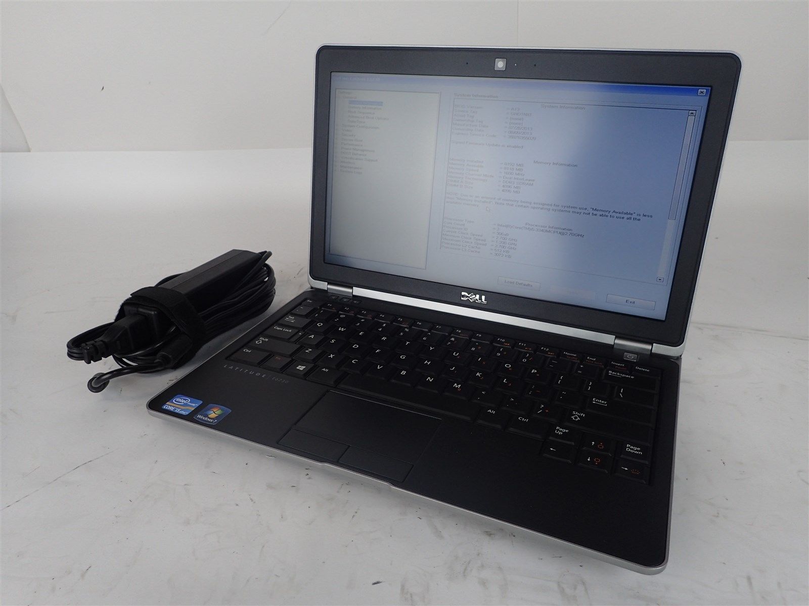
After some hiccups (Yocto needs python2 and GCC <6) I had built a Yocto image and put it on an SD card. Does it boot?
…no
So we can’t boot Yocto because this is a “secure SKU” which means Secure Boot is enabled. Is there some way we can disable Secure Boot? What about updating the BSP to a newer version with Secure Boot disabled?
Back to hardware
If I’ve learned anything from messing around with electronics, you want to make a backup before you start modifying things. This is doubly so if the data in question is related to the booting process. It sucks to end up with a brick, so make a backup!
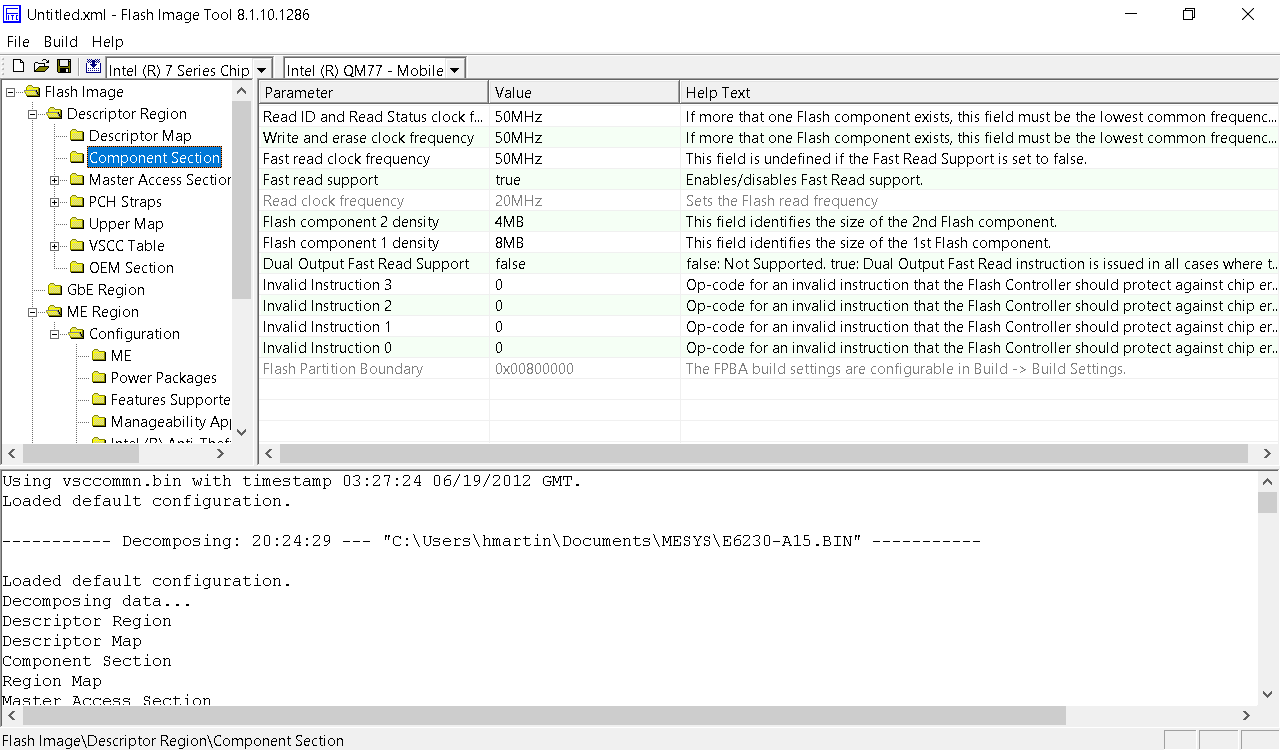
Taking a backup of flash
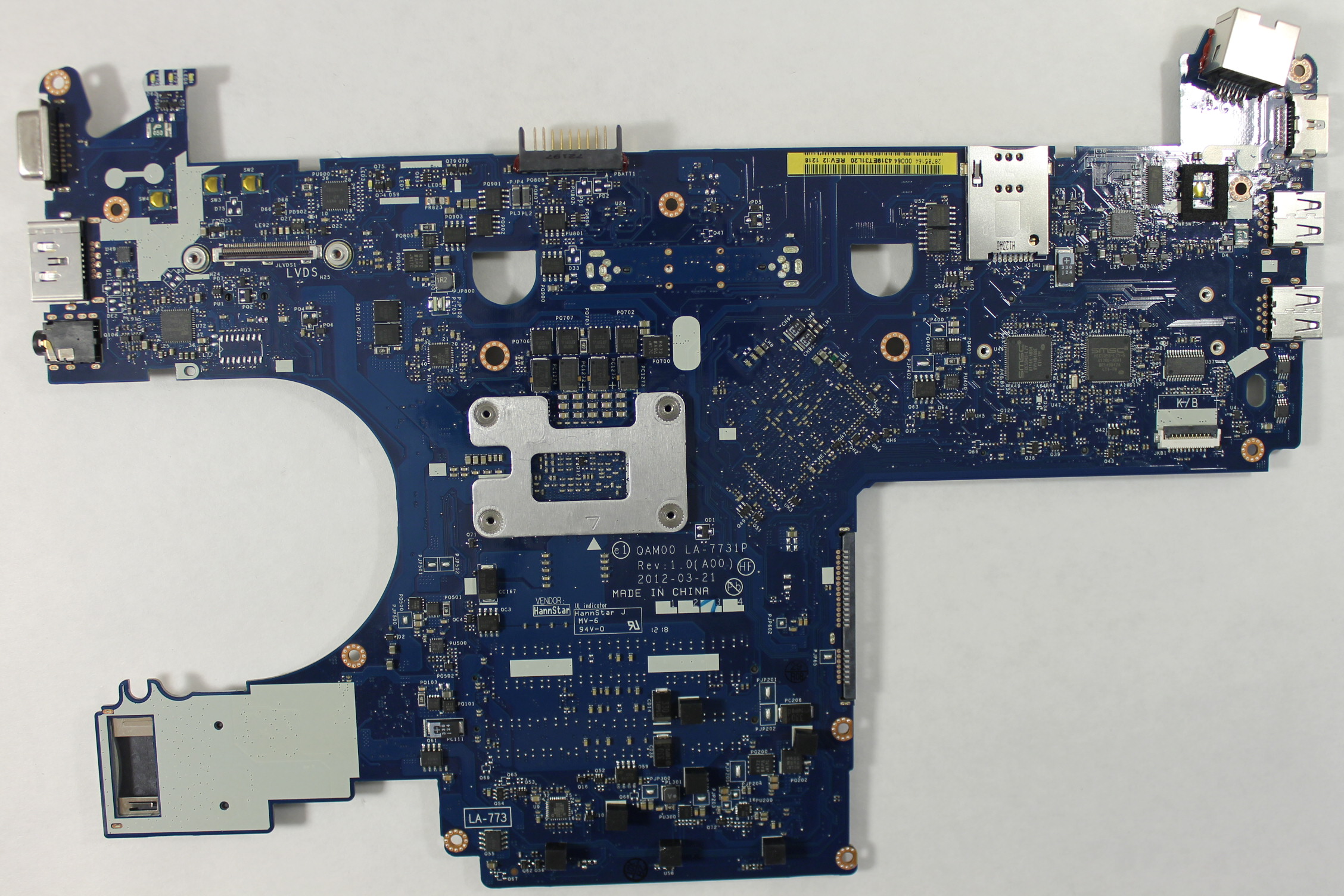
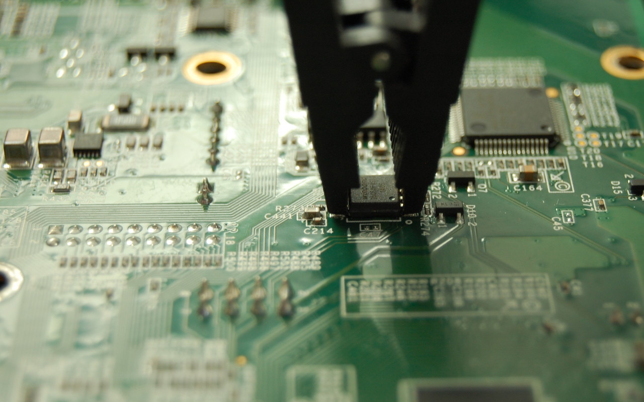
The Intel Quark guide mentions using a Dediprog SF100 to flash EDKII. I don’t have a Dediprog, but I do have an SPI programmer. Unfortunately, none of the Intel documentation I could find mentions the Dediprog header on the DK200, so I had to go hunting.
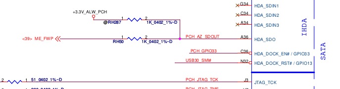
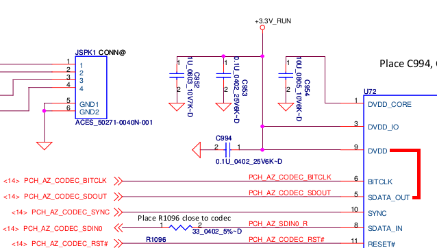
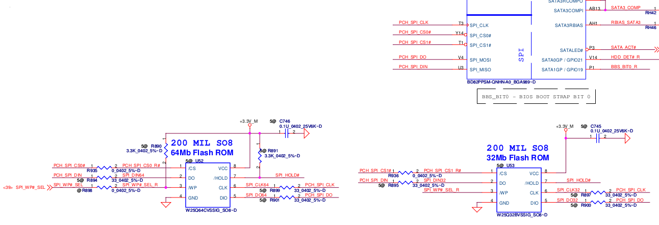
I traced the pins from the Winbond flash to header J23. J23 is only 8 pins, so trial and error with a multimeter to find the pin mapping wasn’t terrible:

J23 pinout
Here’s the pinout of J23 in text form:
| J23 pin | 25Q64 pin | Pin description |
|---|---|---|
| 1 | 8 | VCC |
| 2 | 4 | GND |
| 3 | 1 | /CS |
| 4 | 6 | CLK |
| 5 | 2 | DO |
| 6 | 5 | DI |
| 7 | Not connected | |
| 8 | Not connected |
/WP and HOLD pins on the 25Q64FV are not routed to J23, but they aren’t required for flashing.
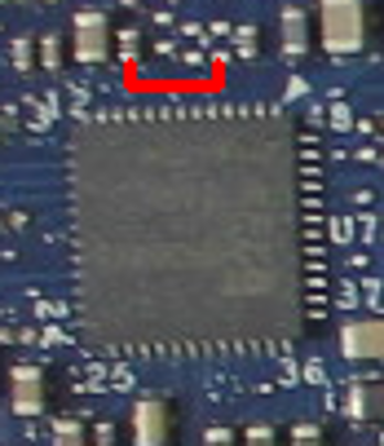
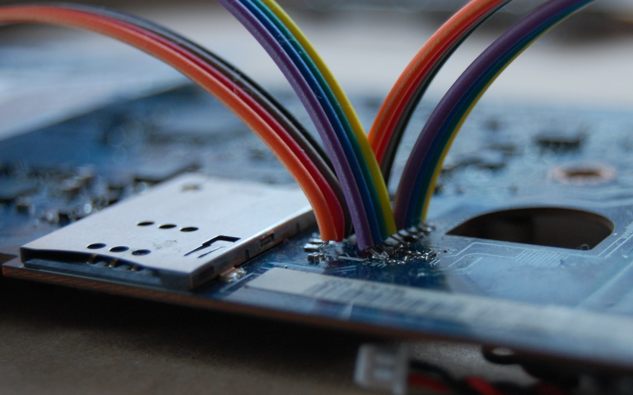
With the pinout known, I could attach the SPI programmer to the header instead of using the chip clip:
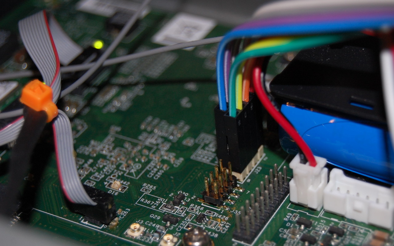
J23 to ch341a SPI programmer
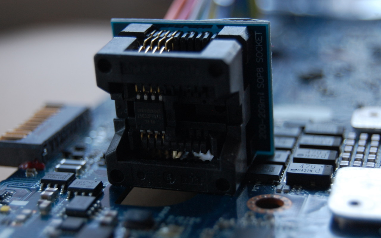
I took a dump of the Winbond 25Q64FV and then for good measure desoldered the chip and read it again to confirm the images were exactly the same. It was strange because the image from the chip clip wasn’t identical. But, the image from the desoldered chip was identical to the image taken from J23, so we’re done here. I wrote the image to a new 25Q64FV and soldered that back onto the board.
Firmware disassembly
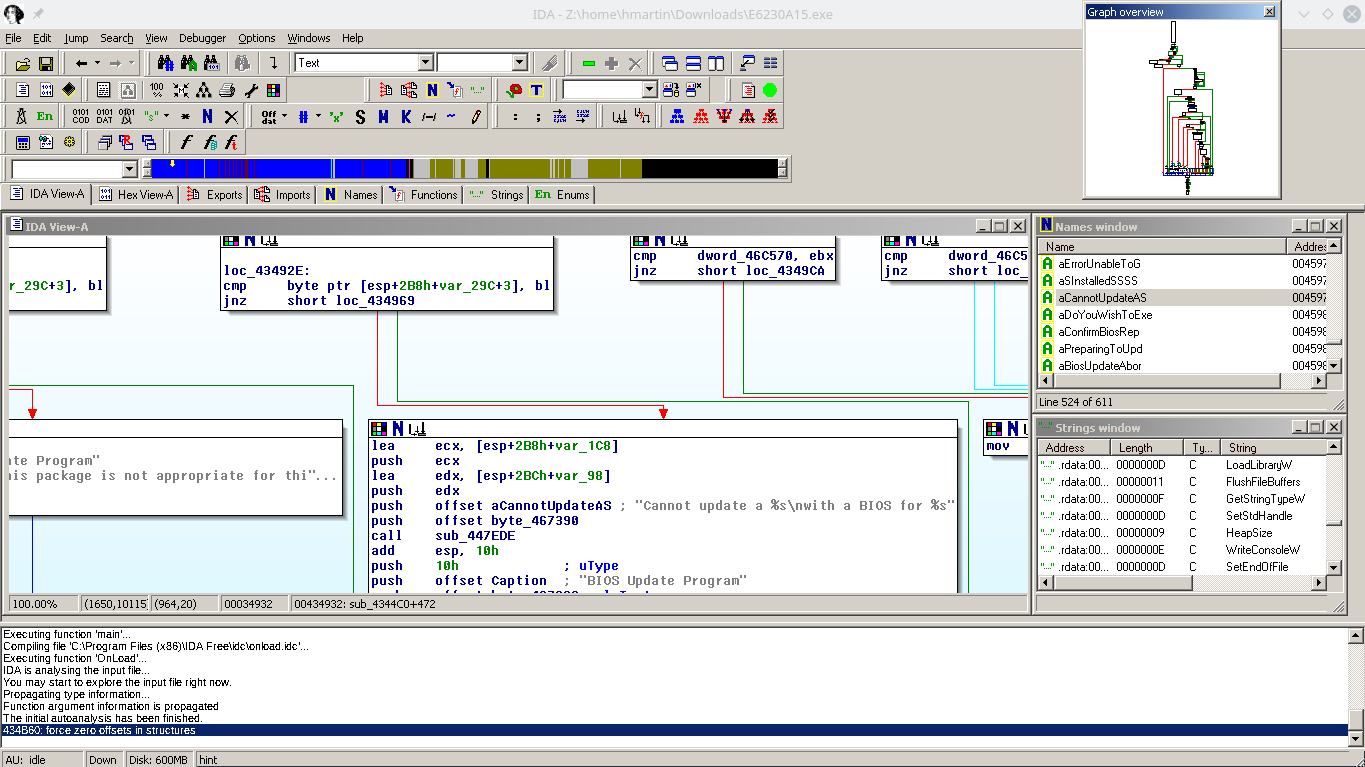
Disassembling the firmware which shipped on my DK200, we see that a Secure Boot certificate was created by WindRiver.
I assume that had I been able to download the WindRiver SDK, I would have been able to build and sign Secure Boot with my own certificates. Given that industrial customers spend a lot of time and money worrying about security, I was surprised to see that the Secure Boot certificate in the firmware was created by WindRiver China.
I did try to load up the image in IDA, but not being a power user of IDA, I couldn’t figure out how to get it to analyze the SPI dump, and gave up to try and compile the firmware from source.
Building the BSP
Being Intel, there are hundreds of pages you can read about developing for EDK2 and other really fun things, probably. I didn’t read them.
A document which I did end up reading religiously was the Intel ® QuarkTM SoC X1000 Board Support Package (BSP) Build and Software User Guide [PDF] which describes how to build all the firmware components needed to bring up the X1000 SoC. I found out there is actually a newer version of this document (1.2.1 instead of 1.1) and there are some important differences between the documents I want to get to later.
By building the firmware, we’re hoping for one of two outcomes:
- A firmware with our own Secure Boot certificates, or
- A firmware which has Secure Boot disabled
Version 1.1 of the BSP Build and Software User Guide includes a section on pages 29 and 30 on how to bundle your own db, kek, and pk certificates:
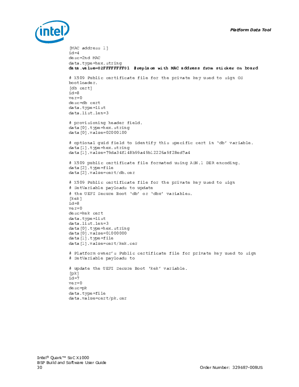
Page 29 and 30 condensed
Unfortunately if you follow the instructions and try to use a layout.conf which specifies these files, you’ll get an error because there’s no address specified for this data in the image:
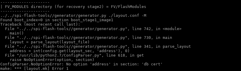
I do have a reference file from WindRiver with Secure Boot certificates, so if I was really interested in making Secure Boot work as intended, I could have reverse engineered the address to store the certificates.
The certificates section of layout.conf was removed from the 1.2.1 revision of the BSP Build and Software User Guide. I guess since it no longer works, Intel decided to remove it from the documentation.
So, we can’t install our own Secure Boot certificates in the firmware. What happens if we just leave out the certificates section entirely and build it?
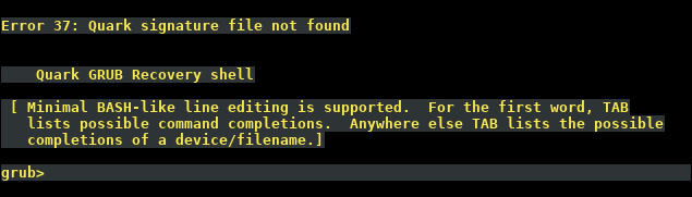
Error 37: Quark signature file not found
Right, so even though there’s now no certificate in the firmware bundle, we still can’t boot.
Interestingly, if you don’t partition the uSD or USB stick correctly, you end up with this pretty screen:
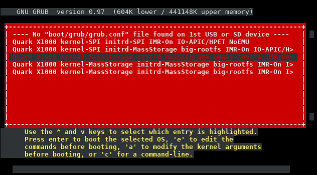
I never saw that in the stock firmware.
Hacking GRUB
So it seems that we can’t include our own Secure Boot certificate in the firmware, due to the sample layout.conf file missing the certificates section, and not knowing the appropriate address to store the certificates.
What if we dig into Error 37: Quark signature file not found a bit more?
If you look in the grub source code included in the BSP, you can see a giant ~1000KB patch that Intel has made to the original upstream code to support the Quark platform.
If you grep for “Quark signature file not found” you’ll find it was added in stage2/common.c:
diff --git a/stage2/common.c b/stage2/common.c

index e96bec2..e122745 100644

--- a/stage2/common.c

+++ b/stage2/common.c

@@ -88,6 +88,8 @@ char *err_list[] =

   [ERR_UNRECOGNIZED] = "Unrecognized command",

   [ERR_WONT_FIT] = "Selected item cannot fit into memory",

   [ERR_WRITE] = "Disk write error",

+  [ERR_QUARK_VERIFICATION] = "Quark signature verification failed",

+  [ERR_SGN_FILE_NOT_FOUND] = "Quark signature file not found",

 };
If you grep for ERR_SGN_FILE_NOT_FOUND you’ll find it’s in the following files:
./work/efi/ia32/loader/linux.c:410:             errnum = ERR_SGN_FILE_NOT_FOUND;

./work/efi/ia32/loader/linux.c:732:            errnum = ERR_SGN_FILE_NOT_FOUND;

./work/efi/quark/boot_settings.c:190:          errnum = ERR_SGN_FILE_NOT_FOUND;
Going back to Intel’s modifications to grub, we can see what they added:
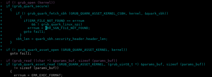
It takes a bit of searching, but if you strip out all of the grub_quark_secure logic from linux.c and boot_settings.c, you end up with…
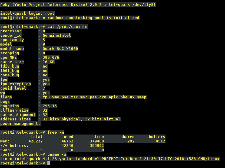
Ta-da! I can boot Yocto Linux
No more Secure Boot!
At the end of the day, the Quark X1000 is an x86: “secure SKU” is nothing but a fuse setting.
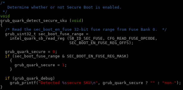
The comment should read:
Determine whether or not grub should enforce Secure Boot.
In our case, this is not a mandatory option 😉
Special offer for DK200 owners
As shown above, it is possible to modify the Intel sources to disable Secure Boot. If there are other people have a DK200 from Intel and are interested in running a firmware without Secure Boot, leave a comment with your contact details. Upon request, I can provide a firmware image* with generic Ethernet MAC addresses for you to flash. Note that this firmware is specific to the DK200 (Clanton Hill) hardware.
* No warranty, express or implied, provided for said firmware image. You flash at your own risk!