Category Archives: Hardware

Resetting Supermicro X10 series BMC to factory defaults

If you’ve ever bought a used Supermicro motherboard and it came without the IPMI login reset to ADMIN/ADMIN, you may be wondering how you can reset IPMI to factory defaults without booting an OS.

Quick note before we continue: if you have an OS on the board, and have installed the IPMI tools for your OS, it’s easier to reset the IPMI username/password via those utilities than via the following method.

This method requires physical access and an SPI programmer like the ch341a or Raspberry Pi. A SOIC16 chip clip will also make life much easier. The ch341a and SOIC16 chip clip can be purchased online for <$10 USD from various sources (e.g. eBay, AliExpress).

Disclaimer: This information is provided without any warranty. Always take multiple physical backups of firmware before performing any modifications. I have only tested this on the Supermicro X10SLE-F motherboard as it is the only Supermicro board I own. However, looking at the REDFISH BMC update image available on Supermicro’s website, this method should be compatible with all X10 series motherboard BMC firmware.

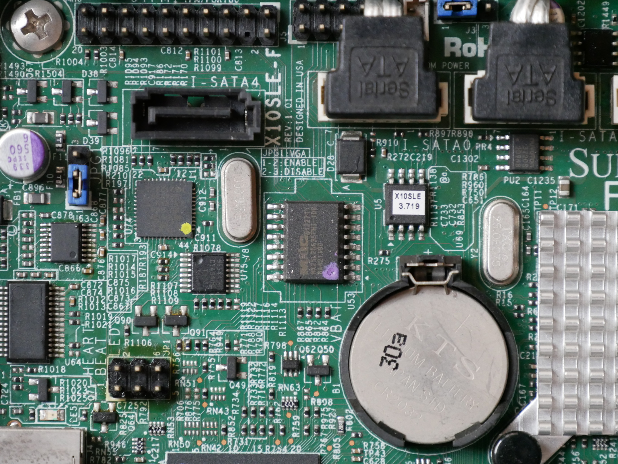
To start, we need to locate the BMC flash. On my X10 board, this is an SOIC16 chip from MXIC with a capacity of 32MB (256MBit).

U53 (SOIC16, 256MBit) contains the BMC firmware, U5 (SOIC8, 128MBit) contains the BIOS

Dump the contents of the BMC firmware using flashrom (using ch341a_spi):

$ flashrom -p ch341a_spi -r BMC.bin

I always dump the flash twice and compare the dumps using a hashing algorithm like sha1 or sha256, to confirm that both dumps are identical.

If they are not identical, check your physical connection to the chip and whether something on the board is receiving power from your SPI programmer.

Using binwalk, find the JFFS2 region. In Supermicro X10 firmwares, this appears to be from 0x100000 to 0x400000:

$ binwalk BMC.bin
DECIMAL       HEXADECIMAL     DESCRIPTION
--------------------------------------------------------------------------------
109381        0x1AB45         Certificate in DER format (x509 v3), header length: 4, sequence length: 12291
109541        0x1ABE5         Certificate in DER format (x509 v3), header length: 4, sequence length: 12291
109777        0x1ACD1         Certificate in DER format (x509 v3), header length: 4, sequence length: 12291
109913        0x1AD59         Certificate in DER format (x509 v3), header length: 4, sequence length: 12291
110057        0x1ADE9         Certificate in DER format (x509 v3), header length: 4, sequence length: 12291
112368        0x1B6F0         CRC32 polynomial table, little endian
1048576       0x100000        JFFS2 filesystem, little endian
4194304       0x400000        CramFS filesystem, little endian, size: 11915264 version 2 sorted_dirs CRC 0xD6771DEA, edition 0, 6818 blocks, 1038 files
20971520      0x1400000       uImage header, header size: 64 bytes, header CRC: 0xC5F4666A, created: 2015-10-05 10:52:56, image size: 1537322 bytes, Data Address: 0x40008000, Entry Point: 0x40008000, data CRC: 0x677BDAA8, OS: Linux, CPU: ARM, image type: OS Kernel Image, compression type: gzip, image name: "21400000"
20971584      0x1400040       gzip compressed data, maximum compression, has original file name: "linux.bin", from Unix, last modified: 2015-10-05 10:49:39
24117248      0x1700000       CramFS filesystem, little endian, size: 5435392 version 2 sorted_dirs CRC 0x43329740, edition 0, 2071 blocks, 309 files

To reset to factory defaults, simply overwrite the JFFS2 region with 0:

$ dd if=/dev/zero of=BMC.bin bs=1 seek=1048576 count=3145728 conv=notrunc

Reflash the modified firmware:

$ flashrom -p ch341a_spi -w BMC.bin

When you power up the board again, the BMC will re-create the JFFS2 region with the default credentials of ADMIN/ADMIN.

Editing the JFFS2 partition instead of overwriting it with zeros seems to invalidate a checksum somewhere, and this causes the BMC to re-initialize the JFFS2 region on the next boot. For that reason, I wouldn’t recommend extracting and editing the JFFS2 region, just zero it out.

Note: you will lose any licensed features in the BMC by resetting it to defaults using this method. However, Peter Kleissner did an amazing job reverse engineering the Supermicro license validation code, and using his work you can generate an IPMI license for your BMC.

With the licensed BIOS upgrade feature of IPMI, you can update the BIOS without ever needing to boot an OS, very handy for when your CPU revision is unsupported by an old BIOS release or if the board happens to have a corrupt BIOS image.

It should also be noted that the Supermicro BIOS updates available from their website appear to be directly flashable to SPI. You’ll lose some SMBIOS information if you use an SPI programmer to write directly to the SOIC8 containing the BIOS, but it can also help resolve some strange issues encountered after the IPMI BIOS upgrade (example below).

I hope this information is useful to anyone trying to get into their Supermicro BMC. Of course, requiring physical access and an SPI programmer is never as easy as resetting the BMC passwords from software and carries some risk that you may corrupt the BMC firmware.


There’s a thread on ServeTheHome about this motherboard if you have any further questions.

Western Digital Weltrend MCU

When we left off in my last post about the Western Digital EX2100, I had corrupted the firmware on the microcontroller responsible for managing mundane system tasks like bringing the main ARM SoC out of reset. This unfortunate bout of curiosity had left me with a fancy brick instead of a NAS.

To recap from the last article, the EX2100 uses a Weltrend WT61P8 series MCU (despite being labelled WT69P803) intended for use in flatpanel televisions. The WT61P8 has a turbo 8052 CPU and is primarily intended for flatpanel television power management as it supports HDMI CEC and Infrared.


Finding the ISP

Consulting the WT61P8 datasheet (PDF) I was able to trace the headers JP3 and JP4 on the EX2100 PCB:
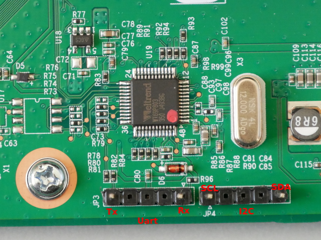
JP3:
Pin 1: Uart Tx (WT61P8 pin 32)
Pin 5: Uart Rx (WT61P8 pin 31)

JP4:
Pin 1: SCL (WT61P8 pin 23)
Pin 5: SDA (WT61P8 pin 22)


If I can be grateful for one thing, it is that this microcontroller is frequently used in Samsung televisions and Russians are very resourceful at repairing and modifying televisions. Through a variety of Russian language forums and with a lot of Google translate, I was able to find that the WT61P8 supports ISP via I2C and that there is software available to flash it. The “Postal2” software is designed for dumping and flashing firmware from televisions, and as the WT61P8 is used in televisions it is supported.

Now my options were either:

  1. Postal2, which is intended to be used with a parallel port to I2C adapter
  2. RT809F ISP programmer, which costs around $70

Since I did not really want to spend money on the RT809F, having no other use for it, I decided to try Postal2.


A trip back to the 1970s

However I faced a problem: Postal2 requires an LPT to I2C adapter, and this is not an adapter you’ll find anyone selling on AliExpress or eBay, so I would have to make it myself.

After searching for schematics, and building one non-functional adapter, I was able to find a correct schematic for an LPT to I2C adapter that people were successfully using with Postal2:
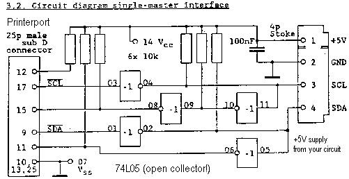
Use 3.3V instead of 5V as the WT61P8 operates at 3.3V

Luckily I already had some CMOS inverters from another project, so I only had to order resistors and an LPT connector. After much soldering, and a trip down nostalgia lane to another era of computing, I finished the adapter:
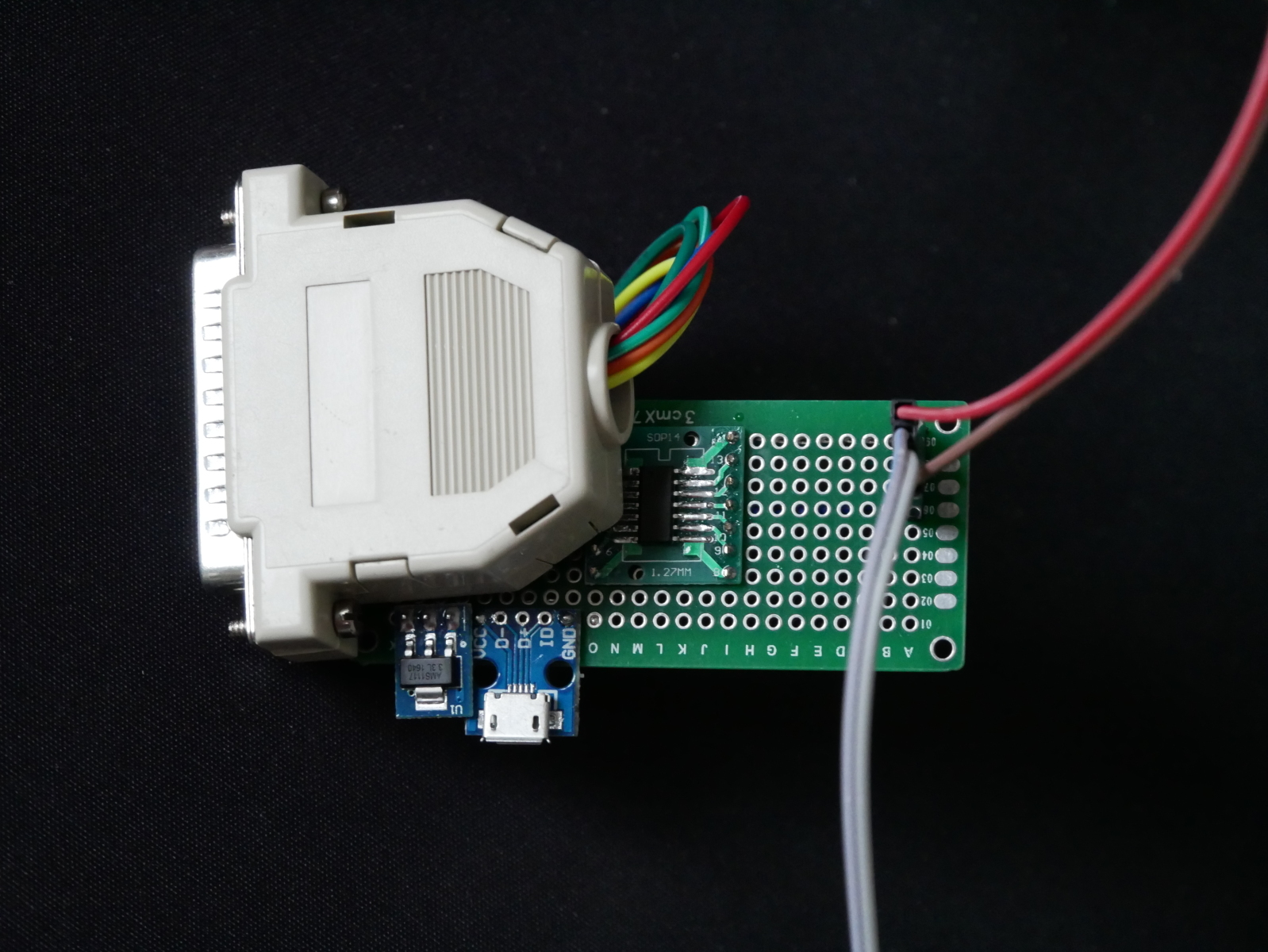
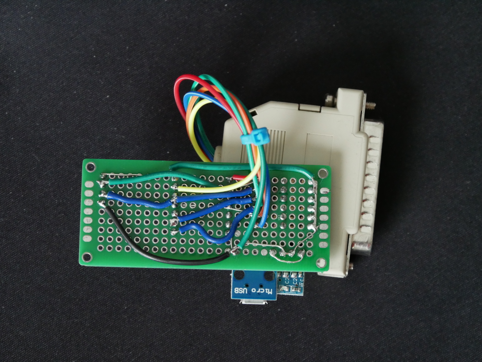
The micro USB port is for power, with a 5V to 3.3V linear regulator. An equal mix of modern and ancient connectors are present in this adapter.

Then I had to find a PC with a parallel port and install Windows 7 x86. Postal2 seems to be completely incompatible with all x64 versions of Windows.


Finally finished with the prerequisite tasks, I started Postal2 and tried to read the current EEPROM contents from the Weltrend using the SDA/SCL lines on JP4 within the EX2100:
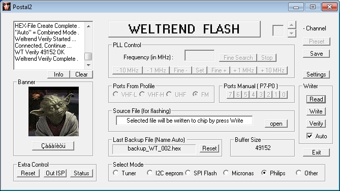
It works!

Examining the downloaded firmware with the firmware file I managed to save from the EX2100 as it was updating, it was clear to me what had happened:

After analyzing the downloaded firmware, it appears mcu_upgrade put the Weltrend into ISP mode and erased a majority of the internal EEPROM, leaving [I assume] only the bootloader. For some reason, mcu_upgrade did not write the firmware back to the Weltrend after erasing. I won’t speculate if my strace on mcu_upgrade was responsible for it… When I reset the EX2100 the Weltrend had no firmware to run, and didn’t bring the main Armada CPU out of reset, resulting in a brick.

Since the bootloader portion of the firmware I dumped and the binary firmware I had from the EX2100 update were the same, I felt confident to upload the firmware binary to the Weltrend using Postal2. My logic: cannot be any more broken than it is now ¯\_(ツ)_/¯
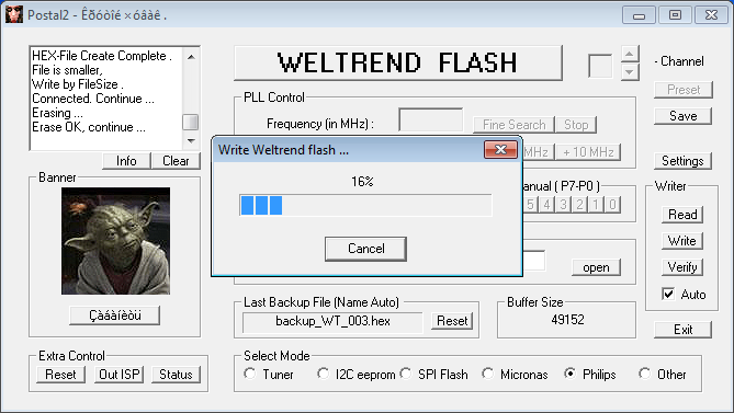

I would not consider the result a complete success. The Weltrend did have a valid firmware again, and it was functional enough to bring the main Armada CPU out of reset. Unfortunately (or predictably) the binary firmware I recovered from the Western Digital update package does not appear to be specifically for the EX2100.

Here is the uart output of the Weltrend during boot before I bricked it:
Yosemite Uart test
nick 2222
nick pwr on
Check_SYSTEM_Command=11
PwrOnCause=10

And here is the uart output after flashing the uP_0.bin I extracted from the EX2100 update archive:
nick 4444
Check_SYSTEM_Command=11
PwrOnCause=00
nick pwr off wol

The codename for the EX2100 is “Yosemite” and unfortunately this string does not exist in the binary firmware uP_0.bin I extracted from the EX2100 firmware update. Looking at the strings in the firmware, it appears that the firmware is intended for the “MyCloudDL2000” (a product that doesn’t exist). There is a DL2100 which is a “Pro” version of the EX2100, using an Intel CPU instead of the Marvell Armada.

Unfortunately the behaviour of the Weltrend with the extracted firmware is different enough that u-boot hangs trying to configure wake-on-LAN for the two Ethernet interfaces. Since u-boot doesn’t get far enough to boot Linux, my next task was stripping out all communication with the Weltrend from the u-boot source to see if I could at least get the NAS to boot Linux.

After building u-boot with WoL configuration disabled, I was able to kwboot u-boot and successfully boot into the Western Digital firmware.

In another stroke of luck, Western Digital has published a new firmware (2.30.181) to resolve a vulnerability discovered in their web management interface. Updating the Western Digital firmware on my EX2100 also updated the firmware on the Weltrend. The firmware update process resolved the issue with u-boot WoL and I had a fully functional unit again.


Obtaining the Weltrend firmware
I was mystified where the firmware from the Weltrend microcontroller came from. There is no file matching the contents of “uP.bin” or “uP_0.bin” in the filesystem of the firmware update, nor is there any firmware blob in the WD GPL archive that I could find.

After much searching in the squashfs filesystem of the update, and through the WD GPL archive, I finally gave up and grepped for a hex string in the firmware in the firmware update binary itself. At this point I was very surprised to find that the Weltrend firmware is simply appended to the end of the WD firmware update.

The firmware is under 50KB, as the size of the flash in the WT61P803 is only 49152 bytes. Chopping the last 50KB of the firmware update file with dd allows you to easily find the offset of the Weltrend firmware with hexdump and grep. The firmware starts with 02 5d a9 which is a long jump to address 0x5da9:


hexdump -C data.bin | grep 02 5d a9

With the offset from hexdump, you can again chop the file with dd to isolate only the Weltrend firmware. There doesn’t appear to be any data in the firmware update file after the Weltrend firmware, so there’s no need to remove any trailing data.


Firmware analysis

I was interested in reverse engineering the Weltrend firmware to determine what tasks it was performing. I know that the Weltrend is responsible for at least:

  1. System power to internal components (Armada CPU, system fan)
  2. Enabling or disabling SATA hard drive power
  3. Reading the ambient temperature sensor
  4. Controlling the system fan speed (PWM controlled)
  5. Power LED (colour, blink rate)

I asked a friend with IDA Pro to disassemble the binary to see if it was possible to isolate specific functions that would give insight into the tasks the Weltrend is performing. Unfortunately, IDA didn’t produce anything immediately obvious. But with some searching, we were able to identify some portions of the firmware, such as the UART command reply method:
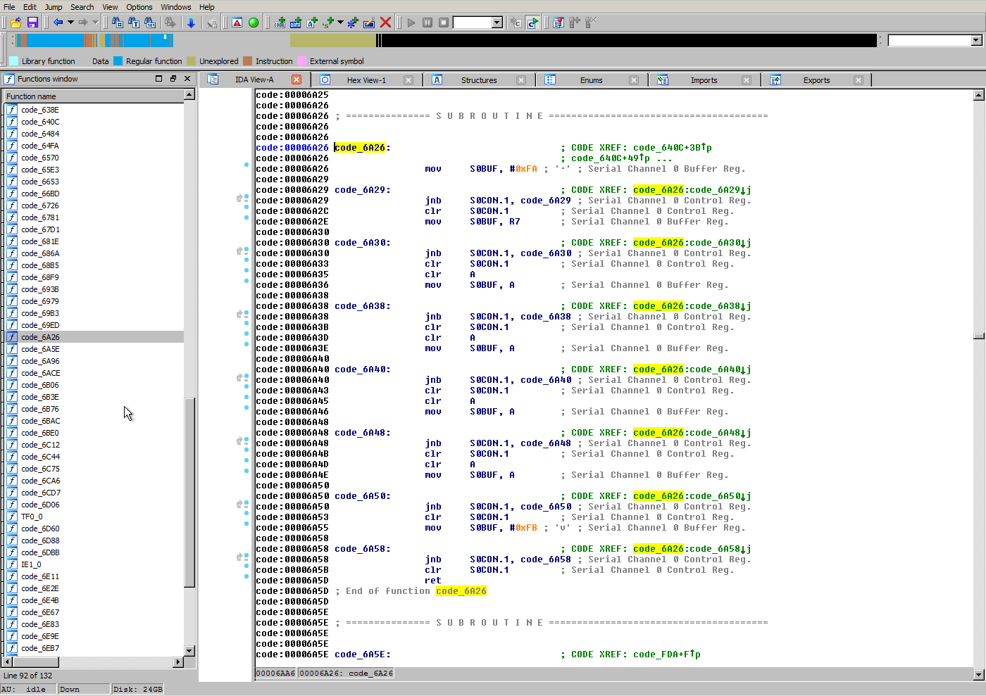
While I dislike an opaque microcontroller being used for important system management functions, I’m not prepared to invest a lot of time in learning 8052 assembly so I can reverse engineer the firmware.


Conclusion

If you have a Western Digital NAS using a Weltrend microcontroller and it appears to be bricked, there is route to recovering the firmware and it’s not as impossible as it may seem at first glance. With access to the SDA/SCL header and an LPT adapter can be built from inexpensive components you can flash the Weltrend firmware extracted from the WD update file.

In the future I think it is best if I stick to the task at hand (writing Debian installation instructions) and refrain from messing with proprietary and undocumented microcontrollers responsible for key system functions like power management.

Stay tuned, installation instructions are coming soon!
CompuLab fitlet2 review

Introduction
The CompuLab fitlet2 is a new model in their fitlet series. The new fitlet2 switches from AMD to Intel’s Apollo Lake SoCs. My unit has the Intel Atom x7-E3950.

First we should discuss the elephant in the room, the fitlet2 is quite small. Here is the fitlet2 compared to a standard 3.5″ hard drive:

Disclaimer: My unit was provided by CompuLab to evaluate its potential as a target for coreboot, and to poke at their firmware (?). I received no compensation for this review, apart from the gratis hardware, and CompuLab did not have any input or influence on the review except to clarify my questions.

In the box
The fitlet2 is quite minimal, in the box you have:

  1. fitlet2
  2. 12V 3A power supply with plugs for AU/EU/UK/US
  3. Small sheet of information (FCC certification, manual download, etc)

There are no other cables or accessories included in the box.

CompuLab use a small form factor port for RS-232, so if you plan to use the onboard RS-232 port, you will need to remember to order the accessory cables package during checkout.

I found the lack of rubber feet a bit strange. The bottom case is slightly elevated thanks to some protruding metal at each corner, but without the rubber feet the device is very slippery on most surfaces. It would be nice if CompuLab included rubber feet in the box that you could apply if you wanted to put the device on your desk.

Hardware

  • Intel Apollo Lake SoC: Atom x5-E3930, Celeron J3455, or Atom x7-E3950
  • Up to 16GB DDR3L-1866 Non-ECC (single SODIMM)
  • M.2 SATA storage
  • M.2 NGFF for WiFi or cellular modem
  • Dual Intel Gigabit Ethernet interfaces (Intel i211)
  • HDMI 1.4b and mini DisplayPort 1.2 outputs supporting 4K resolution
  • Two USB 2.0 and two USB 3.0 ports
  • MicroSD card reader
  • 3.5mm Audio in/out

The CPU in the fitlet2 is low-end. I personally don’t feel there’s any point in trying to talk up the capabilities of the Intel Atom series because they weren’t designed for performance. The Atom specializes as a low power CPU, with the Atom x5-E3930 consuming 6.5W, the Celeron J3455 consuming 10W, and the Atom x7-E3950 consuming up to 12W.

However, there are other areas where the fitlet2 surprises, such as the ability to accept a 16GB SODIMM. The Atom x5-E3930 and x7-E3950 also support ECC memory, although CompuLab confirmed that to offer the Celeron J3455 version they’ve removed ECC support from the motherboard. Be sure to check the fitlet2 RAM Qualified Vendor List (QVL) before purchasing.

Somewhat disappointingly, 4K@60Hz is not supported on both display outputs. This is an Intel Apollo Lake limitation, and will hopefully be resolved in their next generation SKUs. If you want to use 4K@60Hz via HDMI, you’ll need to buy an active adapter to convert the mini DisplayPort output to HDMI 2.0. DisplayPort MST is supported, so you can daisy chain DisplayPort MST capable displays. Unfortunately in my testing I was not able to daisy chain any combination of 4K displays. Daisy chaining two 1080p displays functioned normally. HDMI also functions while DisplayPort MST is active, so in my testing I was able to have three simultaneous 1080p displays driven by the fitlet2. I only have two 4K capable displays, so I’m not able to test all possible display combinations.

The micro SD reader is a nice inclusion, however the slot is so recessed in the front panel I found it impossible to insert or eject a micro SD card with my fingers. I ended up using another SD card to gently push the micro SD into the slot. Even with this helper, I found it difficult to insert and remove the micro SD card. This experience convinced me that if you’re going to use a micro SD card frequently with the fitlet2, an external reader is a must. If your plan is to use the micro SD as expandable storage that is rarely removed, then I don’t think that would be an issue.

My unit came with 4GB of RAM and a 64GB M.2 SATA SSD installed. The M.2 SSD (2242) in my unit is the Kingspec NT-64.

I have been using Kingspec SSDs in low performance applications (such as firewalls) since the beginning of 2017 and haven’t experienced any failures or issues, so while they’re relatively unknown in the West I don’t think they’re necessarily a bad choice. If you want to add a name brand M.2 SSD such as Transcend or ADATA you would probably be better off to buy the barebones model and add the SSD yourself.

The stock model only accepts 7-20V DC input. CompuLab does offer a build-to-order (BTO) version of the fitlet2 which accepts 9-36V DC input.

Software
CompuLab isn’t currently shipping the fitlet2 with any OS. But since the fit-iot website shows a render of the case in the Linux Mint colour scheme, it’s possible they will introduce a bundle with Linux Mint in the future as they have done with past products like the MintBox 2.

I do plan to test Linux, BSD, and Windows 10 IoT on the fitlet2. However I decided to wait on performing any extensive testing or benchmarks until patches for Meltdown and Spectre are available for all the above operating systems. Thoroughly evaluating an OS takes some time, so it may take me some months to get around to reviewing the fitlet2 with the above operating systems (and I have other projects in my pipeline too).

I’m also waiting to hear back from CompuLab on whether they plan to include support for Secure Boot. While some people are against Secure Boot, I think including the option to enable it and letting the user define their own keys would be a wise idea. For hardware intended to be installed in an industrial scenario and left unattended for years in the field, cryptographic verification of the entire boot process is vital to maintaining endpoint security.

Xubuntu 17.10 installs and runs nicely on the fitlet2. Average power consumption at the desktop is around 4.5W. There does appear to be a minor issue with Xubuntu not fully powering off the fitlet2, which CompuLab is aware of and will hopefully be resolved soon.

Conclusion
The fitlet2 is not the smallest x86 platform available (that honour would probably go to the Intel Compute Stick), but certainly offers a lot of I/O and expansion options for its diminutive size.

The fitlet2 is similar, though slightly less I/O rich, to the PC Engines APU2 (Quad Core, 2/4GB RAM, 3x GigE, 3x mPCIe, SD reader) while offering more convenient interfaces like HDMI and DisplayPort for people who don’t live in a 115200 baud world.

The dual Gigabit Ethernet interfaces would make it ideal as a low power firewall or an IoT gateway. Triple display support (DisplayPort MST & HDMI) out of the box could also see the fitlet2 used to power an informational or advertising display. Given CompuLab’s “IoT” marketing for the fitlet2, maybe there will even be a LoRaWAN FACET module available at some point in the future?

For consumers interested in an inexpensive, low power, and fanless PC, the fitlet2 is also functional as a desktop or a small server. It supports multiple displays and has USB3.0, but don’t expect miracles from the CPU or GPU. Worth noting is the stock model doesn’t support WiFi, though there are many inexpensive USB to WiFi adapters which are compatible with Linux and Windows, should you wish to add WiFi later. The fitlet2 also lacks USB Type-C which is supported by Apollo Lake and is slowly becoming more mainstream.

The fitlet2 comes with CompuLab’s standard 5 year return to depot warranty, but CompuLab also offers the Atom x5/x7 models with an extended 15 year availability. This is an important consideration for business customers who want stability in their supply chain or plan to develop and support long-lived products with the fitlet2 (e.g. CNC controllers, PLC applications, IoT gateway).

With barebone models starting from $154 I think the fitlet2 offers good value for the price. I feel CompuLab have a good offering here for the industrial segment as the fitlet2 is much more affordable than previous CompuLab products like the Intense PC, and competing products from companies like Logic Supply.